Shortly before publishing my article on David Kipping’s TARS concept (Torqued Accelerator using Radiation from the Sun), I received an email from Centauri Dreams associate editor Alex Tolley. Alex had come across TARS and offered his thoughts on how to improve the concept for greater efficiency. The publication of my original piece has launched a number of comments that have also probed some of these areas, so I want to go ahead and present Alex’s original post, which was written before my essay got into print. All told, I’m pleased to see the continuing contribution of the community at taking an idea apart and pondering alternative solutions. It’s the kind of thing that gives me confidence that the interstellar effort is robust and continuing.
by Alex Tolley
Dr. Kipping’s TARS proposed system for accelerating probes to high velocity is both simple and elegant. With no moving parts other than any tether deployment and probe release, if it works, there is little that can fail during the spin-up period. There are improvements to the basic idea that increase performance, although this essay will suggest a more complex, but possibly more flexible and performant approach using the basic rotating tether concept.
First, a small design change of TARS to increase the rate of spin-up. The TARS design is like a Crookes radiometer, but working in reverse, with the mirror face of the sail experiencing a greater force than the obverse dark, emissive face. As the tethers rotate, the reflective face increases the spin rate, whilst the emissive face swinging back towards the sun acts as a retarding force. An easy improvement, at the cost of a moving part, is to have the sail reorient itself to be edge-on to the sun as it returns. This is illustrated in Figure 1 below. The rotation can be any mechanism that sequentially rotates the sail by 90 degrees after the tether is aligned with the sun, or other electromagnetic radiation source.
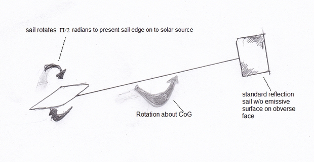
Figure 1. The simplified TARS system with the sail rotating around the tether to reduce the retarding force in the rotation phase.
There are other possibilities to tweak the performance, but at a cost of complexity and added mass.
However, I want to offer an alternative approach that solves some of the limitations of the proposed TARS system.
These limitations include:
- The propulsive force is very phase-dependent as the tether rotates.
- The rotation rate is dependent on the sail aerial density and size<
- The sails add mass to the tether and therefore increase the tether tension, requiring an increased taper
- The TARS rotation must be aligned with the radiation source, limiting the direction it can throw the payloads. This means that a target on an inclined plane to the planets, such as a comet or exoplanet, requires the TARS to take on an inclined orbit, limiting its flexibility.
- The asymmetric forces on TARS change its orbit.
These limitations can be alleviated by eliminating the sails and replacing the rotation with an electric motor, powered by a solar panel. The basic design is shown in Figure 2.
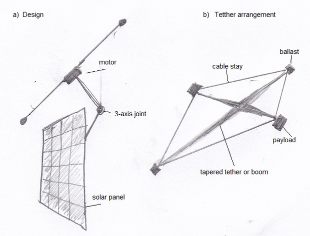
Figure 2. Basic design of a rotating probe launcher using motor-driven tethers.
The tether is powered by an electric motor that requires a counter-rotating wheel or tether (see later) to prevent the system from rotating. This is similar to the power equipment astronauts use in space. The tether is attached to the solar panel by a 3-axis joint to allow full control of the rotational plane of the tether. As the only loads on the tether are its own mass and the releasable probes, the amount of taper should be less than TARS, allowing longer tethers of the same material. The tethers can be flexible or stiff, depending on deployment preferences. Figure 2 shows a preferred arrangement where the tethers form a square, with cable stays to increase rigidity and offset bending during spin-up.
The tether would have 2 releasable probes and 2 small ballasts to maintain tension, or 4 probes. The probes can be released simultaneously in opposite directions, or in the same direction from 1-10 milliseconds apart, depending on the rotation rate. If released in the same direction, the system will tend to be pushed in the opposite direction as the probes released in the same direction would act as propellant, generating thrust in the opposite direction.
A variant would allow for 2 contra-rotating tethers. Because they are mechanically coupled to the same motor, this guarantees that they rotate in synchrony and eliminate the gyroscopic action of a single tether. This removes the need for a counter-rotating disc for the motor, but more importantly, for multiple payloads allows the rotation plane to be changed between payload releases, allowing for different target destinations for the probes to travel in. This would be ideal for a standby to target comets and objects coming from different orbital inclinations, as well as more detailed mapping of the solar system’s heliosphere.
Because the rotation is controlled by a motor, this provides more precise timing of the payload releases. Once the maximum rotation rate is reached, the motor can idle, and the system continue its orbit until the optimum probe[s] release position is achieved, for example when Mars is in opposition. This avoids the continual rotation rate increase of TARS that must release its probe[s] before the tethers snap.
So what sort of rotational speed can a motor provide? The maximum speed for a small motor is 100,000 rpm, or 1667 rps. A much lower speed is achieved by hard disk drives at 7200 rpm or 120 rps.
This translates to:
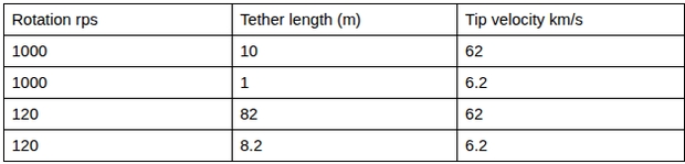
Because the rotation rate is so fast, any probe release must be timed with very high precision to ensure it travels on the correct flight path towards its destination. While not critical for some missions, encounters with small bodies such as interstellar objects (ISO) like 2I/Borisov will require very high precision releases.
Unlike TARS, the tethers can also be spun down, making the system reusable to reload the payloads. If multiple payloads can be released sequentially like a Pez dispenser, then these can be reloaded periodically when the payloads have been exhausted. With extra complexity, these cartridges of probes could be carried on the system, and attached to the tethers after the rotation has been reduced to zero, making the device relatively autonomous for long periods.
Lastly, because the rate of rotation acceleration is dependent on the motor and power available, the power can be increased with a larger solar array, and the motor torque increased with a larger motor. These are independent of the tether design, making any desired upgrades simpler, or like CubeSats, configurable on manufacture before launch.
This is a great mass driver concept, but it can be made even greater by dispensing with the wasteful spin-up/spin-down process. There is no reason the payloads could not be continuously fed from the hub to the tip along the tether while the tether is under constant rotation. Such a device would have near 100% energy efficiency.
Also, longer tethers are better. They reduce the rotational period and maximum acceleration, and decrease the timing accuracy requirement. So, practical devices will likely involve tether lengths in the 1-100 km range.
The longer the tether, the greater the tension on it. I haven’t thought too much about the angular rotation rate vs the increased tension due to greater mass. I assumed that Dr. Kipping’s design with a 12.1m tether was optimized for this and wanted to keep the alternative version closer to that bound with a 20m tether (10m radius at least for 3 examples).
Yes, one could feed payloads from the center to the periphery. That imposes more complexity and mass, and bending forces on the tether. I think there is also momentum transfer, the moving payload slows down the rotation rate as it travels to the periphery. [See the classic ice skater spin rate slow as the arms are extended.] However, it does offer the capability of having many more low-mass payloads without incurring more tension than if they were all on the end of the tether.
I don’t think longer tethers mean higher tension. Length goes up and rotation rate goes down. It cancels out.
The ENORMOUS gain in throughput and energy efficiency from eliminating spin-up and spin-down outweighs, by far, the added complexity of a radial transport system. A rope and pulley would do the trick. A slower, longer tether would make that easier.
Of course the radial transport would exert a force on the tether, that’s how the momentum is imparted. The motor needs to do work to keep the rotation rate constant as payload moves towards the tip. That work is what imparts the kinetic energy on the payload.
Let me clarify. For the same tip velocity, a longer tether with a slower angular velocity has LOWER forces than a shorter tether with a higher angular velocity. If the angular velocity is constant, the tension increases, but you get a higher tip velocity.
The longer the tether, the more difficult it is to deploy and manage, and the mass increases. This was experienced during an experimental tether deployment during the Gemini manned space program (IIRC).
After Mike Serfas & Adam ran the forces at the tip calculation, I ran a number of scenarios down to around 1000 g with slow rotating, but very long tethers (20,000 km). We know from the approximately 350,000 km tapered tether from the Moon to geosync, with a maximum of 1g near Earth, that a lightly tapered tether of the best high tensile plastics will break if lengthened further. 1000 g is going to need a steep taper, even with graphene or CNT. The TARS images show the tether looking like a sail. My guess, without doing the calculations, is that a long tether would need a huge base width to support itself, let alone even a small payload, and still be able to provide a several km/s velocity to the payload. This implies a large tether mass. The lunar space elevator cable mass was substantial, with a small, or zero, taper. You can read the details in the reference paper from my CD post: Spaceline: A Design for a Lunar Space Elevator.
At this time, I think that the g-forces at the tip, while not breaking the tether, will prove problematic on the payload. If the payload needs to navigate to a point destination, like a planet, it will need a propulsion unit, such as a solar sail. This sail will need to be undeployed until it is released. Yet it will experience severe deforming forces on a delicate sail that would probably prevent a successful deployment from some compact form into a flat sail.
If correct, Dr. Kipping should investigate this to see if it is a problem and whether it can be mitigated or not. If not, then TARS won’t work as outlined.
I actually think tether mass does NOT increase with length. For given tip velocity, as length goes up, acceleration goes down. For a given payload mass, then, the cross section of the tether needed to hold the payload decreases in proportion to length, leaving the total mass constant.
You are right. I was wrong. The forces decrease in the same proportion as length increases, for the same tip velocity. At its simplest, if the cable has no taper, then the number of constant X-section cables to hold any given mass will increase with the tip forces, with a total mass the same as a longer single cable with slower rotations and decreased forces. Although I cannot visualize the taper, it seems to me that the same must be true.
Thanks for the correction.
For delicate payloads, including crew, several hundred km are needed, I think. Very feasible, nevertheless.
I think that a crew module is best accelerated by a mass driver. These have appeared frequently in fiction from A C Clarke’s Maelstrom II, to Ian McDonald’s Luna trilogy, as well a popsci such as O’Neill’s lunar mass drivers for colony materials.
The issue of very long tethers, for transport of people and cargo from the Moon to geosynchronous orbit, has been studied, including possible materials. Here, the tension is due to Earth’s gravity tugging on the cable, rather than rotation. A Martian surface-to-areosynchronous orbit cable was indicated in A C Clarke’s The Fountain’s of Paradise that was kindly mentioned to me by frequent essayist and commenter LJK.
I have Space Tethers and Space Elevators (2009) by Michel van Pelt that goes into more detail about how tethers can be used in various space applications. On p20, he talks about tethers as linear launch catapults, but not as a rotation device for a space-based launcher. In this regard, TARS may be a truly novel approach.
A tether sling is the most economic mass driver. 1000 km of tether is many orders of magnitude cheaper and lighter than 1000 km of rails and superconducting magnets or whatever else an electromagnetic mass driver would require. Yet, it can do the same job, more efficiently and at higher throughput.
As far as I know, neither Pelt nor anyone else has considered constantly rotating motor driven tethers with the payload transported radially from the hub. It appears to be a common oversight.
The main use of tethers for propulsion is slow-rotating tethers to allow momentum exchange with no need for propellant. Van Pelt does describe a linear cable as a “mass driver”. For ascent to orbit, skyhooks or sky cranes using rotating tethers are attractive, but they do need a way to reacquire lost momentum, usually by balancing both inward and outward bound traffic.
Wouldn’t you agree, though, that “neither Pelt nor anyone else has considered constantly rotating motor driven tethers with the payload transported radially from the hub”?
I have searched far and wide, and while there is work that comes close, none has all the features.
If you use carbon nano tubes and the probe can withstand the very high accelerations it may be better to have the probe at the centre of the spacecraft and a dumb mass at the tip. On breaking a nanotube has a wave propagation speed that is around a 1000km/s. In effect you use the rotational velocity and the stored energy in the tensioned nanotube.
@Michael.
I don’t see the connection between wave propagation velocity and the velocity of the cable as it snaps under tension. Are you suggesting that the tip would move at 1000 km/s when a wave in the tether reaches the tip?
AFAIK, the only movement is the lateral movement of the tether as the wave passes. The same as in water, the wave velocity is far greater than the circular velocity of the water molecules. The wave doesn’t mean that anything physical moves in the same direction as the wave velocity. If it did, the tether would immediately snap as the wave started.
It is teh same with the sound wave propagation. The sound wave moves very fast, but the material in the teher does not move at all.
The propagation wave is the maximum velocity the tether would know so for a brief time as the tether relaxes back the force is concentrated at the break with a lot of energy. I think the maximum strain for a nanotube is 5 to 20% so for say a 100 m cable that’s a decreasing acceleration over 5 to 20 m/s.
A problem I haven’t seen addressed is the timing of detaching the probe. The timing (=aiming of the probe) will have to be incredibly precise to be sure the probe meets its target instead of passing it millions of kilometers away
Yes. With incredible timing and accuracy for “point” destinations. The probes had best have their own sails that can navigate to overcome this. For destinations such as exploring the heliosphere and ISM, this is not such an issue.
Some tether related thoughts…
For heavier probes, might a Centaur tethered to a science-craft be able to sling a small probe to a target otherwise unreachable by inclination.
An upper stage not able to reach a target on its own can at least yet a probe off to the side.
This is the only way you can “turn” in space without needing the gravity of a large planet, or brute force NSWRs.
Might TARS be a way to slow an inbound object?
A way to reverse a Sundiver?
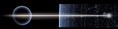
What would this look like to observers here on Earth?
For the 10 meter line, omega is 2pi * 1000/s radians. Omega squared r is 395 Mm/s^2 = 40 million Earth gravities. Now in biology, centrifuges of 60,000 xg are impressive, but supposedly, Iranian nuclear centrifuges can reach 500,000 xg now.
If 10 meters of the line can withstand an average of 20 million Earth gravities pulling down on its weight, that means that 200,000 km of the line can withstand one Earth gravity of pull. This meets the specs for space elevator line.
Now if it could hold 1 kg at this speed, 1/2 x 1 kg x (62832 m/s)^2 = 1.974 GJ. So the system (if dominated by payload) would store an energy density of 1974 MJ/g, far in excess of any known rocket fuel.
This is the key number allowing the system in this or the previous article to work – yet so far, as far as I know, flywheels have not surpassed chemical fuels for energy storage. Why are people now convinced they can store much more energy than that?
@Mike Serfas, Adam
Thank you for doing the calculations I should have done myself.
Assuming a maximum g force of 10,000g on the probe at the tether end, the best configuration is a very long tether radius and slow rotation –
rotation: 1 rps,
tether radius: 2 km,
launch velocity: 12.6 km/s
g force: 8000
(assuming I have the calculations correct).
Slow down the rotation further, and extend the tether radius to a rather improbable length, and the g forces can be maintained, but the launch velocity increases.
rotation: 0.1 rps,
tether radius: 200 km,
launch velocity: 126 km/s
g force: 8000
rotation: 0.01 rps,
tether radius: 20000 km,
launch velocity: 1256 km/s
g force: 8000
But these forces would break a uniform tether, and the width of a tapered tether would become untenable for such radii.
AFAICS, the TARS paper does not consider g forces on the payload, just the forces on the tether related to its tensile strength. So the large taper, as depicted in the videos, may keep the tether intact, but the forces may be problematic for the payload. Certainly, the magnetic version that increases the rotation rate would vastly increase the g forces on any payload, making this just a magnetic shield and not some interstellar launch vehicle.
Superficially, at least, this may prove to be the Achilles’ heel of TARS as a high-velocity launch vehicle.
I’m not sure about the relevance of energy storage of flywheels vs chemical fuels. Sure, they are insufficient for vehicles, but so are batteries for long-distance aircraft. The energy density is too low. But there are applications where energy density is not relevant, and cost is. So flywheels for short-term storage of renewable energy can work, as can other physical approaches, most notably pumping water uphill to reservoirs. So energy (solar or beamed) can [slowly or quickly] accelerate a sail to high velocity. This is fine as long as the vehicle doesn’t have to store the potential energy in its entirety before it is used for work, moving it.
There is a direct relationship between maximum tip velocity and material specific strength for tethers, independent of length. 10 km/s is a stretch, only reachable with carbon fiber and a large amount of taper. That this limitation is similar to that of chemical rockets is no accident. Both combustion and material cohesion are based on chemical bonding as the fundamental mechanism. That’s also why flywheel energy density limits are similar to those of chemical fuels.
According to my calculations, assuming we can stretch material and taper to 12.6 km/s, a 500 km long tether could launch payloads with moderate, human tolerable acceleration of 5 g. The rotation rate would be a leisurely 0.004 revolutions/s, or one revolution / 4 minutes.
I made a 2pi mistake in those calculations. It will take a 3000 km tether to accelerate to 12km/s at 5g. The rotation period would be 25 minutes.
I think I seen somewhere an energy density of around 1 to 3 mega joules/kg far below chemical storage. But it can release it at a very high rate when it snaps for instance.
Fun Fact: The specific strength of materials has the unit of velocity squared. That velocity is the maximum rim velocity of a flywheel, or the maximum tip velocity of a tether, multiplied by a geometry factor on the order of one.
Another fun fact: trying to increase the geometry factor much beyond one runs into exponential limits reminiscent of the rocket equation. Again, no accident. In a way, tether taper is analogous to rocket staging.
I wanted to know the mass ratio (mass of tether/mass of payload) of an optimally tapered tether based on tip speed and length. Being lazy, I asked Grok, and I received this phenomenal detailed treatment of the problem, which seems to be absolutely correct:
https://grok.com/share/c2hhcmQtMw%3D%3D_cef58422-2106-46f5-bc08-d70dc6f0b037
I am dumbfounded at the speed and accuracy of this derivation, which occurred in a matter of seconds, and this is not even the strongest version of Grok, by far.
The results confirm what I said, the mass ration rises exponentially with the tip speed, similar to the mass ratio in the rocket equation.
Can you download a copy of the Grok output with the nicely formatted equations and create a PDF? Then pass it to Paul to email me. I cannot download the full Grok output and if I copy it to Google docs, I lose the equation formatting, perhaps because it is missing a javascript library for rendering the equations.
I want to keep it for future reference.
I have a PDF. I will have Paul relay it to you!
Sorry for spamming the list, but I find this incredibly interesting. This is the last one, I promise!
Given the results of the taper computation, the maximum geometry factor that is practical (mass ratio<1000) is around 3, i.e. the maximum tip speed is three times the square root of the specific strength of the tether material. That comes to around 6 km/s for a real material such as Zylon, and around 20 km/s for a theoretical material made out of carbon nanotubes. Strengths are from here:
https://en.wikipedia.org/wiki/Specific_strength#Examples
Eniac, you’re a long-time presence here and your posts are always on point and insightful. Definitely not spam!
Thanks, Paul!
If this is correct, it should be kept as a permanent heuristic “factoid” to temper such designs.
Hi Alex
Whew! Not sure a payload is going to survive the gee-forces of a tip-speed of 62 km/s if the tether is 10 metres in radius. 1000 rps is 6.28 kiloradians per second angular velocity, meaning the gee forces are 40 MILLION gees.
What about a shorter tether with probes on either end?
An asteroid runs into the tether–with the two ends whiplashing at high but manageable g-forces.
Each probe then perhaps inflate/deploy some sail area while coasting.
The problem is not with the idea of using a spinning object for propulsion, but with how to achieve the spin and forward motion. Using radiation photon pressure would with light and dark ends would cause spin in space, but it wouldn’t have any forward motion. This can only be achieved using gravitational effects as electromagnetism does not have much of a thrust and its force is only short range. There have already been many tests with electromagnetic drives and the thrust is too low. I still like the idea though, but it can’t be solved by today’s technology, but only the propulsion science of the future.
I worked on this problem myself in the year 2007 to explain some spinning spheres and disks I saw in binoculars over my city. Nasa’s Breakthrough Propulsion Physics Program papers explained it.
Hi Alex & Paul
I am a fan of the obscure and under-appreciated reference or precedent for a concept. The whole discussion reminds me very strongly of Edward Everett Hale’s “The Brick Moon” (1869) which posits storing the energy to fling the titular Brick Moon into orbit in gigantic fly-wheels that have been powering up for months care of a handy river’s flow. Of course, the tale is somewhat whimsical, but fly-wheels are still useful energy storage systems for such applications.
I think SpinLaunch shows that this partially works for rocket launches. We’ll see how the technology develops.
The problem with such approaches to reach orbital velocity is that the rocket must be travelling in excess of orbital velocity to account for drag. But a rocket entering even the thin atmosphere from space undergoes immense heating, and this would be far worse at ground level, even from on top of a high mountain 10km high.
I suppose a brick moon has a natural ceramic hull to ablate off the surface. ;-)
The flywheel at least overcomes the extremely high g forces of Verne’s cannon.
It seems that electrostatically-supported TARS would be ultimately limited by the same factors as a simple one. TARS is, in essence, a flywheel which is spun up by solar radiation. In the limit, rotational energy of a flywheel is equal to tensional energy and the latter is limited ultimately by energy of chemical bounds, as it is noted in the paper. Exponentially-tapered geometries allow for some energy focusing, but again, it is very similar to Tsiolkovsky equation applied to rockets, so velocity gain is logarithmic.
Electrostatic force can counter centrifugal one but the paddles themselves will stretch because like charges on them repel from each other. In absense of electric breakdowns, this would limit their charge by their own tensile strength, after which Coulomb explosion would follow.
I tried an example calculation with rotational velocity of 50 km/s. If the limiting acceleration is 25 kilo-gees, then r is 10 km. Then, if paddle mass is 1 kg, it would need F = 100 kN of electrostatic force to held it in orbit. Since F = k*Q**2/r**2 where k is 1/(4*pi*eps_0), Q = sqrt(F*r**2/k) = 33 Coulombs. The electrostatic energy of a charged sphere is E_q = 0.6*k*Q**2/r_paddle = 6 Terajoules if r_paddle == 1 m. Since paddle mass is 1 kG, this is already six orders of magnitude greater than energy of chemical bounds, and Coulomb explosion is inevitable. More, the voltage on the paddle surface would be E/Q = 200 gigavolts, so the paddles need to be charged by powerful perticle accelerators, working constantly against influx of ions and electrons from solar wind. Even if paddles are charged bubbles with r_paddle == r_orbit, then E_q is 600 MJ per kg mass, which is the same OOMAG as the kinetic orbital velocity (it should be somewhat greater but I likely dropped some coefficients).
Checking this,
F = v**2*m/r = k*Q**2/r**2; v**2*m*r = k*Q**2;
Q = sqrt(v**2*m*r/k) = v*sqrt(m*r/k)
E_q ~ Q**2 ~ v**2 ~ m_paddle ~ r_orbit, which seems to be correct.
If r_paddle == r_orbit (two touching bubbles), E_q = 0.6*k*v**2 * (m*r/k) / r = 0.6*m*v**2 * (k/k) * (r/r) ~ kinetic energy.
In ‘touching bubbles’ configuration, With larger orbital radii, voltage decreases and seems to become manageable, but thickness of paddle surface decreases which leads to increasing tension. For this study case, it already is below atomically-thin limit.
While your calculations are way above my pay grade, your point about the solar wind offsetting the charges is relevant.
The solar wind would be countering the charges, which would need to be replenished. I think this is similar to the electric sail that needs to keep ejecting particles (electrons) that are attracted to the +ve charged wires, for the same reason.
IIRC, some years ago, there was a CD post about using 2 [?] phased charged grids to accelerate the solar wind as a propulsion device. It was a novel idea to harness the solar wind that way. I think that it wouldn’t work as the phased charging could not ensure a tight pulse of particles (protons) to be attracted to the grid, then pass through it when the -ve charge was stopped, to be repelled by the 2nd grid with +ve charge after they passed behind it. The local build-up of electrons as the protons were accelerated away would also be a problem.
Such sail would be made of two grids, and there is an issue of electromagnetic forces between them. If such phasing could be made, the force is likely attractive and it will collapse the sail. But the point is that solar wind is plasma, and a plasma thruster could be made using it.
I like an another idea more – a single sail made from fine grid, and an electron beam which is fired in the downwind direction. The sail needs to be charged so that solar wind ions just barely pass through. They are repelled to some extent while they approach, but once they passed through, they are accelerated by much greater electric field of dipole consisting of the sail and space charge of the electron beam, resulting in some net thrust even using DC.
At first glance, this should work and accelerate the sail into the upwind direction, so the speed is not limited by the solar wind itself. Not sure about the overall efficiency, but since magsails and electric sails could intercept all solar wind coming at them, then this kind of sail should utilize it quite efficiently, too. Maybe even with better efficiency than lightsails (but that’s mainly because efficiency of photon thrust is rather poor at v << c). Of course, while such spacecraft does not carry working fluid with it, it still needs lots of energy, from an advanced extremely lightweight nuclear reactor, maybe.
@torque_xtr
Your calculations are very pertinent and confirm the intuition that it is impossible to accumulate enough charge such that its electrostatic attraction or repulsion would be greater than the cohesion of the material the device is made of.
Your observation of the fundamental role of chemical bonding in the limitations of flywheels and rotating tethers is also right on.
There is another thing that limits specific mechanical energy. Tethers and flywheels break at the weakest point, and if they are made with defectless single crystals, weak points are created continuously by thermal lattice vibrations. This matters really much. For macroscopic objects, there are always some places where these vibrations momentarily create something like rogue waves where lattice is locally weakened dramatically. Under high stress, failure starts from such points and spreads globally, so the limit to stored mechanical energy is always many times smaller than cohesive energy. Maybe cooling to near-absolute-zero would improve this to some extent, but this adds a whole new level of complexity, and still there are ground-state quantum vibrations which are always present.
In contrast to this, stored chemical energy is equal to full energy of chemical bonds which are affected during it’s release. So, in some way, slingshot-type launchers/boosters will always fall short of limits for chemical rockets, and they need some other advantage to become competitive. And, to go beyond chemical limits to delta-V, something else is needed.
What is the significance of the rotation? I assume that it is supposed to be part of the propulsion? What is the physics of how the angular momentum of the rotation is transferred into forward motion is not explained in this and the previous paper. AI thinks electromagnetism from solar wind would cause a spin, but no forward motion.
There is no forward motion. All TARS does is rotate and release the actual probes when they reach the highest velocity at the ends of the rapidly rotating tether. TARS stays in something similar to a statite orbit that Kipping calls a quasite orbit.
If an asteroid comes up from behind a tether with a probe at either end (the tether pointed north/South or east/West along the plane of the ecliptic)–the strain on the tether will not be as great.
The two probes yeeted could have TFINER tech.
These sling-launcher concepts raise some interesting mission design problems. Can one design a mission in which two spacecraft of equal mass (but possibly non-identical design), equal initial position, and opposite initial velocity each go on to find useful (but possibly quite unrelated) things to do?
More generally, the two spacecraft could be of unequal mass, and launched from an asymmetric tether with velocities opposite in direction but unequal in magnitude.
The initial launch position does not need to be near Earth, or even in the inner Solar System, as the tethered system could use its solar sails (or other means) to escape from Earth orbit during the spin-up phase of the mission.