Centauri Dreams
Imagining and Planning Interstellar Exploration
Future AI: The Explorer and the Philosopher
Robert Bradbury had interesting thoughts about how humans would one day travel to the stars, although whether we could at this point call them human remains a moot point. Bradbury, who died in 2011 at the age of 54, reacted at one point to an article I wrote about Ben Finney and Eric Jones’ book Interstellar Migration and the Human Experience (1985). In a comment to that post, the theorist on SETI and artificial intelligence wrote this:
Statements such as “Finney believes that the early pioneers … will have so thoroughly adapted to the space environment” make sense only once you realize that the only “thoroughly adapted” pioneers will be pure information (i.e. artificial intelligences or mind uploaded humans) because only they can have sufficient redundancy that they will be able to tolerate the hazards that space imposes and exist there with minimal costs in terms of matter and energy.
Note Bradbury’s reference to the hazards of space, and the reasonable supposition — or at least plausible inference — that biological humanity may choose artificial intelligence as the most sensible way to explore the galaxy. Other scenarios are possible, of course, including humans who differentiate according to their off-Earth environments, igniting new speciation that includes unique uses of AI. Is biological life necessarily a passing phase, giving way to machines?
I’ll be having more to say about Robert Bradbury’s contribution to interstellar studies and his work with SETI theorist Milan ?irkovi? in coming months, though for now I can send you to this elegant, perceptive eulogy by George Dvorsky. Right now I’m thinking about Bradbury because of Andreas Hein and Stephen Baxter, whose paper “Artificial Intelligence for Interstellar Travel” occupied us yesterday. The paper references Bradbury’s concept of the ”Matrioshka Brain,” a large number of spacecraft orbiting a star producing the power for the embedded AI.

Image: Artist’s concept of a Matrioshka Brain. Credit: Steve Bowers / Orion’s Arm.
Essentially, a Matrioshka brain (think dolls within dolls like the eponymous Russian original) resembles a Dyson sphere on the surface, but now imagine multiple Dyson spheres, nested within each other, drawing off stellar energies and cycling levels of waste heat into computational activities. Such prodigious computing environments have found their way into science fiction — Charles Stross explores the possibilities, for example, in his Accelerando (2005).
A Matrioshka brain civilization might be one that’s on the move, too, given that Bradbury and Milan ?irkovi? have postulated migration beyond the galactic rim to obtain the optimum heat gradient for power production — interstellar temperatures decrease with increased distance from galactic center, and in the nested surfaces of a Matrioshka brain, the heat gradient is everything. All of which gives us food for thought as we consider the kind of objects that could flag an extraterrestrial civilization and enable its deep space probes.
But let’s return to the taxonomy that Hein and Baxter develop for AI and its uses in probes. The authors call extensions of the automated probes we are familiar with today ‘Explorer probes.’ Even at our current level of technological maturity, we can build probes that make key adjustments without intervention from Earth. Thus the occasional need to go into ‘safe’ mode due to onboard issues, or the ability of rovers on planetary surfaces to adjust to hazards. Even so, many onboard situations can only be resolved with time-consuming contact with Earth.
Obviously, our early probes to nearby stars will need a greater level of autonomy. From the paper:

On arrival at Alpha Centauri, coming in from out of the plane of a double-star system, a complex orbital insertion sequence would be needed, followed by the deployment of subprobes and a coordination of communication with Earth [12]. It can be anticipated that the target bodies will have been well characterised by remote inspection before the launch of the mission, and so objectives will be specific and detailed. Still, some local decision-making will be needed in terms of handling unanticipated conditions, equipment failures, and indeed in prioritising the requirements (such as communications) of a multiple-subprobe exploration.
Image: Co-author Andreas Hein, executive director of the Initiative for Interstellar Studies. Credit: i4IS.
Feature recognition through ‘deep learning’ and genetic algorithms are useful here, and we can envision advanced probes in the Explorer category that can use on-board manufacturing to replace components or create new mechanisms in response to mission demands. The Explorer probe arrives at the destination system and uses its pre-existing hardware and software, or modifications to both demanded by the encounter situation. As you can see, the Explorer category is defined by a specific mission and a highly-specified set of goals.
The ‘Philosopher’ probes we looked at yesterday go well beyond these parameters with the inclusion of highly advanced AI that can actually produce infrastructure that might be used in subsequent missions. Stephen Baxter’s story ‘Star Call’ involves a probe that is sent to Alpha Centauri with the capability of constructing a beamed power station from local resources.
The benefit is huge: Whereas the Sannah III probe (wonderfully named after a spaceship in a 1911 adventure novel by Friedrich Mader) must use an onboard fusion engine to decelerate upon arrival, all future missions can forego this extra drain on their payload size and carry much larger cargoes. From now on incoming starships would decelerate along the beam. Getting that first mission there is the key to creating an infrastructure.
The Philosopher probe not only manufactures but designs what it needs, leading to a disturbing question: Can an artificial intelligence of sufficient power, capable of self-improvement, alter itself to the point of endangering either the mission or, in the long run, its own creators? The issue becomes more pointed when we take the Philosopher probe into the realm of self-replication. The complexity rises again:

…for any practically useful application, physical self-replicating machines would need to possess considerable computing power and highly sophisticated manufacturing capabilities, such as described in Freitas [52, 55, 54], involving a whole self-replication infrastructure. Hence, the remaining engineering challenges are still considerable. Possible solutions to some of the challenges may include partial self-replication, where complete self-replication is achieved gradually when the infrastructure is built up [117], the development of generic mining and manufacturing processes, applicable to replicating a wide range of components, and automation of individual steps in the replication process as well as supply chain coordination.
Image: Stephen Baxter, science fiction writer and co-author of “Artificial Intelligence for Interstellar Travel.” Credit: Stephen Baxter.
The range of mission scenarios is considerable. The Philosopher probe creates its exploration strategy upon arrival depending on what it has learned approaching the destination. Multiple sub-probes could be created from local resources, without the need for transporting them from Earth. In some scenarios, such a probe engineers a destination planet for human habitability.
But given the fast pace of AI growth on the home world, isn’t it possible that upgraded AI could be transmitted to the probe? From the paper:
This would be interesting, in case the evolution of AI in the solar system is advancing quickly and updating the on-board AI would lead to performance improvements. Updating on-board software on spacecraft is already a reality today [45, 111]. Going even a step further, one can imagine a traveling AI which is sent to the star system, makes its observations, interacts with the environment, and is then sent back to our solar system or even to another Philosopher probe in a different star system. An AI agent could thereby travel between stars at light speed and gradually adapt to the exploration of different exosolar environments.
We still have two other categories of probes to consider, the ‘Founder’ and the ‘Ambassador,’ both of which will occupy my next post. Here, too, we’ll encounter many tropes familiar to science fiction readers, ideas that resonate with those exploring the interplay between space technologies and the non-biological intelligences that may guide them to another star. It’s an interesting question whether artificial general intelligence — AGI — is demanded by the various categories. Is a human- or better level of artificial intelligence likely to emerge from all this?
The paper is Hein & Baxter, “Artificial Intelligence for Interstellar Travel,” submitted to JBIS (preprint).

Artificial Intelligence and the Starship
The imperative of developing artificial intelligence (AI) could not be more clear when it comes to exploring space beyond the Solar System. Even today, when working with unmanned probes like New Horizons and the Voyagers that preceded it, we are dealing with long communication times, making probes that can adapt to situations without assistance from controllers a necessity. Increasing autonomy promises challenges of its own, but given the length of the journeys involved, earlier interstellar efforts will almost certainly be unmanned and rely on AI.
The field has been rife with speculation by science fiction writers as well as scientists thinking about future missions. When the British Interplanetary Society set about putting together the first serious design for an interstellar vehicle — Project Daedalus in the 1970s — self-repair and autonomous operation were a given. The mission would operate far from home, performing a flyby of Barnard’s Star and the presumed planets there with no intervention from Earth.
We’re at an interesting place here because each step we take in the direction of artificial intelligence leads toward the development of what Andreas Hein and Stephen Baxter call ‘artificial general intelligence’ (AGI), which they describe in an absorbing new paper called “Artificial Intelligence for Interstellar Travel,” now submitted to the Journal of the British Interplanetary Society. The authors define AGI as “[a]n artificial intelligence that is able to perform a broad range of cognitive tasks at similar levels or better than humans.”
This is hardly new terrain for Hein, a space systems engineer who is executive director of the Initiative for Interstellar Studies, or Baxter, an award-winning and highly prolific science fiction novelist. A fascinating Baxter story titled “Star Call” appears in the Starship Century volume (2013), wherein we hear the voice of just such an intelligence:
I am called Sannah III because I am the third of four copies who were created in the NuMind Laboratory at the NASA Ames research base. I was the one who was most keen to volunteer for this duty. One of my sisters will be kept at NASA Ames as backup and mirror, which means that if anything goes wrong with me the sentience engineers will study her to help me. The other sisters will be assigned to different tasks. I want you to know that I understand that I will not come home from this mission. I chose this path freely. I believe it is a worthy cause.
What happens to Sannah III and the poignancy of its journey as it reports home illuminates some of the issues we’ll face as we develop AGI and send it outward.

Image: A visualization of the British Interplanetary Society’s Daedalus Probe by the gifted Adrian Mann.
On the one hand, deep space mandates our work in AI, leading to this far more comprehensive, human-like intelligence, while at the same time human activities in nearby space face directly into the fact that space is a hostile place for biological creatures. There may develop evolutionary offshoots from Earth’s human stock as pioneering colonists move to Mars and perhaps the asteroids, tapping cyborg technologies and perhaps beginning a posthuman era.
I notice that in Martin Rees’ new book On the Future, the famed astrophysicist and Astronomer Royal speculates that pressures such as these may lead to the end of Darwinian evolution. Developing AGI would replace it with artificial enhancement of intelligence directed by increasingly capable generations of machines. It’s a conceivable outcome, and it’s one that would emerge more swiftly away from Earth, in Rees’ view. The need for powerful AGI for our explorations beyond the Kuiper Belt could well be a driving force in this development.
Of course, we don’t have to see future AI as excluding a human presence. One science fiction trope of considerable interest has been what Andreas Hein explored in earlier work (see Transcendence Going Interstellar: How the Singularity Might Revolutionize Interstellar Travel). One option for exploration: Send probes equipped with AGI to create the colonies that humans will eventually use. Could AGI raise a generation of humans from individual embryos upon arrival?
We can also think about self-replication. A first generation of probes could, as Frank Tipler and Robert Freitas have discussed, continually produce new generations, resulting in a step-by-step exploration of the galaxy.
Whether or not humans go with them or send them as humanity’s emissaries will depend on the decisions and technologies of the time. We have rich background speculations in science fiction to rely on, which the authors tap to analyze AI and AGI for a range of interstellar scenarios and the consequent mission architectures.
Thus AXIS (Automated eXplorer of Interstellar Space), the creation of Greg Bear in his novel Queen of Angels, which runs its own scientific investigations. Long-time Centauri Dreams readers will know of my interest in this novel because of the issues it raises about autonomy and growing self-awareness in AI far from human intervention. AXIS is an example of what Hein and Baxter refer to as ‘Philosopher’ probes. These are probes that, in contrast to probes with specific missions, are able to support open-ended exploration.
Probes like this are able, at least to some extent, to use local resources, which could involve manufacturing, hence the potential wave of new probes to further destinations. Agile and adaptive, they can cope with unexpected situations and produce and test hypotheses. A ‘Gödel machine’ contains a program that interacts with its environment and is capable of modification as it searches for proofs that such changes will produce benefits for the mission. Such a machine, write the authors, could “…modify any part of its code, including the proof searcher itself and the utility function which sums up the rewards…” and could “…modify its soft- and hardware with respect to a specific environment and even set its goals.”
‘Philosopher’ probes deserve more exploration, which I’ll get into tomorrow. But Hein and Baxter develop a taxonomy that includes four types, distinguished in terms of their objectives. We’ll need to look at samples of each as we consider AI and AGI as currently envisioned. The mix of formal and qualitative analysis available in this paper opens many a speculative door, pointing toward the paper’s design of a generic AI probe and predictions about AI availability.
The paper is Hein & Baxter, “Artificial Intelligence for Interstellar Travel,” submitted to JBIS (preprint).
The Next Steps in Space
Most of my research for Centauri Dreams involves looking at papers and presentations on matters involving deep space, whether propulsion systems, closed loop life support, or even possible destinations. That’s why it’s a huge help to get an article like the one below, giving us an overview of current thinking and an analysis of what is either in the pipeline or under consideration for the near-term. How do we get from here to the kind of Solar System infrastructure we’ll need to go interstellar? Ioannis Kokkinidis has an impressive background: He holds a Master of Science in Agricultural Engineering from the Department of Natural Resources Management and Agricultural Engineering of the Agricultural University of Athens. He went on to obtain a Mastère Spécialisé Systèmes d’informations localisées pour l’aménagement des territoires (SILAT) from AgroParisTech and AgroMontpellier and a PhD in Geospatial and Environmental Analysis from Virginia Tech. Today Ioannis surveys the lay of the land, from near-future manned missions to robotic forays to Jupiter, Saturn, the ice giants and beyond.
by Ioannis Kokkinidis

Introduction
This post was inspired from a reader’s comment that came in my review of Andy Weir’s Artemis at this website: most people are not aware of what are the planned future plans for space exploration beyond the highly publicized plans of SpaceX. I noted then that I might write in the future about the future of space exploration as it is outlined in the current plans, rather than just the dreams of visionaries. Furthermore 2019 is the 50th anniversary of the first moon landing, and people are probably wondering what is supposed to come next. In this post I review what the current plans to explore space from earth orbit to interstellar space look like currently, both for robotic and human spaceflight. My standard caveat that these are the views of a learned amateur, not a professional in the sector, applies as always.
Earth orbit
Since this is a blog on interstellar travel, I will keep my analysis on earth orbit short. Suffice to say that for robotic exploration even a simple listing of all the future satellites that are planned to be put up by various public and private agencies can fill volumes of books. For human spaceflight it is certain that this particular destination will not be abandoned. The International Space Station is currently authorized until 2024 and there has been legislative action to extend it all the way to 2030. This is something to consider when evaluating the feasibility of the Planetary Society’s Mars in the 2030s plan, which expects that ISS money will go to Mars Exploration after the station is abandoned in 2024 or 2028 at the latest. Even if ISS is abandoned in 2030, NASA will not abandon the destination. There are currently very preliminary plans about a successor space station that will not be owned by NASA, but by a private contractor with NASA leasing space for use by its astronauts. This is a similar model to what ESA uses, which plans in the future to keep sending its astronauts to earth orbit stations it will not own. Russia still has several modules to add to its segment of the International Space Station, starting with Nauka MLM-U. When the time comes to abandon the current ISS, Russia will detach its new modules and turn them into an autonomous space station. China also intends to keep sending its own space stations to low earth orbit, and ESA has signed a cooperating agreement to send its own astronauts there. India has its own plans to achieve orbit autonomously.
Maintaining a station in earth orbit makes sense from a deep space perspective: you would want to first test how your astronauts will react to space in the cloistered environment near earth before sending them off to farther destinations where they will face increased risks. There are plans to put up private space stations as hotels and, if the ISS proved anything, is that there are several people willing to pay an 8 digit price tag to experience space. Whether these plans actually come to fruition remains to be seen. My understanding is that private trips to the ISS ended with the retirement of the Space Shuttle and its logistics capacity, even though all private travelers came by Soyuz. The problem with private space stations is that the current market will not support a privately owned station. The ISS receives some $100 million in private income per year; there is a figure on the web that private space research is about $500 million per year which sounds a lot until you consider that for Fiscal Year 2018 US Congress appropriated over $4 billion for ISS operations and related activities such as commercial cargo and crew. To that we would need to add spending by the other ISS partners. Future space stations would need to function more cheaply and attract more funding just to cover operation costs, let alone assembly costs.
The Moon
The moon is the most accessible destination beyond earth, 600 times closer than Mars. China has given an emphasis on the moon with its Chang’e program, which can lead to human landings. Russia intends to return to the moon with the Luna-Glob program, which will be missions Luna 25 through 31. South Korea intends to send a rover to the moon, with US participation. India has sent an orbiter, Chandrayaan-1, which had US participation, and which it intends to follow up. SpaceIL of Israel is about to send the first private mission to the Moon, funded by philanthropy rather than government appropriations. The US intends to send robots to the lunar surface and has solicited the private sector for lunar landing architectures. The program is called the Commercial Lunar Payload Services program and has awarded 10 contracts, initially for a user manual to the landing architecture, that can reach up to $6.2 billion in awards. Many of those participating have come out of the defunct Google Lunar X Prize. Those plans though are dwarfed in excitement by the plans for a return of people to the moon.
Orbit
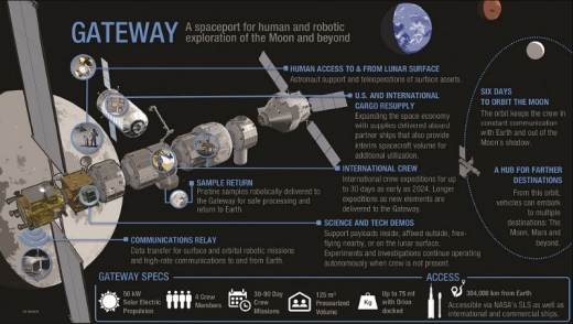
Image: Plan of the Lunar Orbital Gateway. Credit: From the December 7 2018 presentation to the NASA Advisory Council Human Exploration committee.
The next great frontier of human space exploration is currently planned to be Earth’s Moon. Of course this can sound a bit oxymoronic: didn’t we first orbit the Moon 50 years ago with Apollo 8, and go on to orbit it another 8 times? That is very true, but we have not been there since Apollo 17 in 1972. The Soviet Union abandoned its moonshot after the fourth N-1 rocket exploded in 1974, and by then NASA had focused on the earth because of the backlash to Apollo. A plan for a partially crewed station in lunar orbit emerged at the start of this decade, proposed by the contractors of the International Space Station when their work assembling it had finished. During the Obama presidency it was sold as proving ground for the Journey to Mars: a prototype of the Mars transfer habitat loosely connected to the earth but not very far away. Currently the Moon itself is the final destination: rather than have the Altair lander that would be carried with Orion per the Constellation program plan, another lander is to be used that will go from the currently dubbed Lunar Orbital Platform Gateway (LOP-G) to the lunar surface and back. The Gateway will be in a Near Rectilinear Halo Orbit and will be crewed only part of the time, just as Skylab and the early Salyut stations were. The first section will be the Power and Propulsion Element which will be an adaptation of current spacecraft buses for geostationary satellites; it is expected to proceed from the conceptual to the development stage in 2019 and launch in 2022. While it will be launched by a commercial rocket to earth orbit and proceed using its own high power electric propulsion engines to the Moon, that will not be the case for the other modules. Starting from Exploration Mission 3 each Orion launch to the Moon will carry with it a module that will be dropped off at the station until it is assembled.
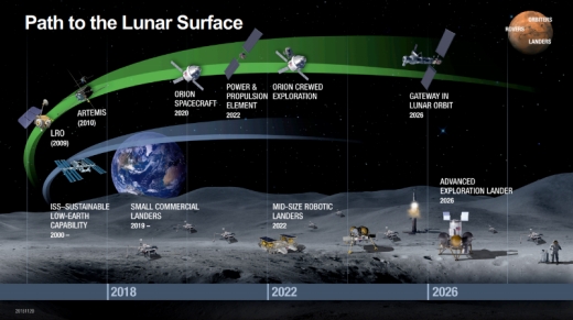
Image: Overview of the Gateway plan. Credit: From the December 7 2018 presentation of Jason Crusan to the NASA Advisory Council.
The Gateway has many critics. For starters many people are opposed to it because it will use the Space Launch System and the Orion Spacecraft: “Any money not spent on SpaceX is a waste, SLS is a waste, Orion is a waste, government is waste, private sector forever”. It is true that the origins of the Space Launch System is the Senate; the Obama administration wished to abolish all of the George W Bush era Constellation program and let the private sector do everything. The Senate stopped this continued the Orion spacecraft as a deep space vehicle and created the SLS as a continuation of the Ares V rocket. Congress did not allow Nixon to abolish NASA because it had become a jobs program; this was also the case for the end of Constellation. The Congressional delegation of Alabama is not about to send thousands of jobs and millions in funding from Huntsville to California, nor are the delegations of any other of the 41 states that have SLS contractors. At least Jeff Bezos has been wise enough to put his rocket factories in established rocket manufacturing areas, Elon Musk did not. If anything, the cancellation of Space Shuttle proved that Congress will not automatically re appropriate money saved to other NASA programs: NASA was not given saved shuttle funding and it was used instead to pay other government priorities. NASA funding rose again only after The Martian film came out and Congress got more interested in human space exploration.
Another set of critics point out that it would be more advantageous to launch bigger pieces of the Gateway on their own dedicated SLS launches rather than try to fit them behind the Orion. This is a very valid point; Mir was sent up separately from the cosmonauts that assembled it. Yet another criticism is that Lunar Orbit is a destination where we should put a station after we have a station on the surface of the moon, and that it will be nothing but a toll station, an unnecessary stop on the way to the Moon’s surface. Better yet, let’s put up an orbital station after we have proven In Situ Resource Utilization, if at all. Having a station in lunar orbit and a spaceship that can go there is far more technologically mature than having a surface station. We have had stations in Earth orbit since Salyut 1 in 1971. By now we know what it takes to run one, though how it will function and how astronauts will function semi-detached from the earth is an unknown. Beyond the short surface forays with the Lunar Modules during Apollo, we do not have any experience operating on the surface of another body. On top of that, the lunar surface is a rather harsh place, with 14 (earth) day days and nights with wild temperature swings and an ever present and harsh dust. Also having a space station in lunar orbit is creating infrastructure that helps make lunar exploration more sustainable, as was emphasized to the NASA Advisory Council. Furthermore it is much easier to resupply from Earth a lunar orbital station than a surface station that would require soft landing of the goods sent. What is certain in any case is that the orbital station at the moon has matured enough as a plan that there is a real notional assembly plan expected to be done by 2026. Surface base plans are far more notional, mostly pursued by space advocates.
Surface
The most developed idea to colonize the Lunar Surface is ESA director Johann-Dietrich Wörner’s Lunar Village. The idea is that all the world nations will come together and build a joint settlement on the moon where one building will be from ESA, another from NASA, another from Roscosmos and so on. Wörner has used his authority at ESA and earlier at DLR (German Aerospace Research Center) to fund a few conceptual architectural studies on how a building from regolith would look. There has not been though real development on a plan with milestones and dates to build the village, unlike the LOP-G plan. While NASA has put up tenders for the Gateway with technical descriptions for the modules and there is a preliminary agreement on what the modules should be, there is no such planning for the lunar surface. Russia has proposed a lander from the Gateway to the surface, and so has Lockheed Martin, using a version of its Mars Lander proposal from the Journey to Mars but without a heat shield.
China intends to directly land on the moon at the end of the Chang’e program, possibly in the 2030s. It was announced in the press conference for the first lunar night of Chang’e 4 that Chang’e 8 “will test key technologies to lay the groundwork for the construction of a science and research base on the Moon”. What this means practically is unknown, Chang’e 4 also tested a key technology to construct a base by having an experiment to grow plants and insects on the moon. Apollo plans for longer lunar stays were for a modified version of the Lunar Module without an ascent stage to be used as a habitat for a lunar day while the astronauts would use the Lunar Module on which they arrive only for descent and ascent to the surface. Later the Apollo Application Program envisioned a soft horizontal landing of the upper stage of the Saturn V with the Oxygen tank converted into a long term habitat, per the wet workshop concept.
Post Apollo plans for the most part envision a core module, similar to a space station module, landed on the lunar surface and then covered with regolith for radiation protection using a bulldozer, before longer term construction begins. Specific Chinese base plans have not been announced. The characteristics of the Chinese space program are that it is highly focused but maintains a glacial pace. When the Chinese sent the first person to space in 2003 the Greek magazine Ptisi kai Diastima (Flight and Space) had a comprehensive review of what was known and what had been announced about the Chinese manned space program showing that the effort to send a person in space had begun around 1980. If the Chinese have indeed decided to send a person to the Moon and build a base there, it will happen, eventually. However the decision making process in space, as in many other domains in the People’s Republic of China is quite opaque.
The American (and European) system is quite open, but less focused. The US has vacillated between a return to the Moon and forward to Mars as a destination for human spaceflight for decades, depending on the presidential administration. At least for robotic spaceflight, the US scientific community has created the Decadal Surveys process to create a consensus among the various scientific interests on what destinations and investigations are to be prioritized. China works with 5 year plans, but there is no publicly known long term roadmap in either human or robotic exploration. The Chang’e 4 press conference announcements, which also mentioned a Chinese Mars rover for 2020 have so far been the most public long term plan announced.
Venus and Mercury
Venus and Mercury are grouped together in this post because both will mostly remain the purview of robotic spacecraft. The Apollo Applications Program seriously considered a Manned Venus Flyby for 1974, but in the end the only part of AAP that came to fruition was the least risky one: Skylab. Several Mars plans have included a test at Venus, usually as a dress rehearsal to a Mars mission. Venus is closer and requires less energy to visit than Mars, so before sending a spacecraft on a 15 month mission to Mars, we can send it on a six month mission to and from Venus. Still, the surface of Venus is a sulfuric hellhole, very hard to visit by robot, and there are very few unique things that require human participation to do in orbit, especially considering that the planet does not have any satellites. Recently a Venus airship was proposed as part of NASA’s Advanced Innovative Concept program. Balloons have been dropped on Venus, most recently two French balloons that were part of the Soviet VEGA mission to Halley’s Comet, but this is to my knowledge the first proposal for a crewed dirigible. NASA AICs are at best decades from fruition and most are never implemented.
Venus has proven to be the greatest success of the Soviet space program. Russia has plans to send another probe in the future, Venera D, which will have US participation. Currently the Japanese probe Akatsuki is orbiting Venus. Earlier, ESA’s Venus Express was doing so, but the US has not sent a mission since Magellan in the early 1990s. There have been proposals both in the Discovery and New Frontiers programs but they were not selected. For this reason NASA’s planetary division is investigating a Venus Bridge mission, something that will cost around $200 million and can do more science than Magellan. Also a surface mission is being contemplated. The state of technology is such that a cooling shield at Venus can work for some 5 hours before it fails, and then we can try to have a hot mission as long as the robot lasts. There is some computer hardware out there able to withstand Venusian conditions such as a CPU, but not an entire computer, e.g. no high temperature RAM.
Mercury has the disadvantage of being in a location where the energy necessary to reach it is similar to that needed to reach Jupiter. So far we have had Mariner 10 do three flybys, MESSENGER orbit the planet and ESA’s BepiColombo is on its way there. The US National Academy of Science suggests that the next mission there ought to be a lander. Considering how sporadic missions to Mercury have been and that no Mercury lander has been proposed yet, it will take quite some time until such a mission starts.
Mars
The Red Planet has been the object of popular fascination throughout the telescope era. As David Portree has noted in his book Humans to Mars, over 100 mission architectures have been proposed for a human landing there since Von Braun’s Der Marsprojekt of 1948, but none has yet moved to building the necessary equipment. On the other hand, while Mars has very appropriately been described as the graveyard of space probes, it has also been the setting of spectacularly successful robotic missions. The next big step in robotic missions to Mars is Sample Return. So far the only time that a mission proposal for Sample Return reached the definite launch date phase, at least per Ulivi and Harland’s book series Robotic Exploration of the Solar System, has been the JPL 2003 proposal, which was cancelled after the twin failures of the 1999 missions revealed that “Faster, Cheaper, Better” also meant too much risk. However NASA has persisted and the current sample return architecture looks as such: First a rover will land and cache samples on the Martian surface. That rover is the Mars 2020 rover which is under construction at the Jet Propulsion Laboratory. Then another mission will land that will have a fetch rover which will pick up the samples and bring them back to the return launcher, which in turn will lift them to Mars orbit. There another spacecraft will collect them and return them to earth. So far these two missions have not been authorized, but there are plans. Now that we do know what the weight of the sample cache is, the older plans for a solid rocket liftoff rocket had to be revised: it would be too heavy. Thus a hybrid rocket architecture was selected, and currently there is active development to mature this technology so that it can be used. The notional timeline is that the fetch mission will be launched in 2024 and ESA has signed a preliminary agreement to provide the return spacecraft. However there is also a far more ambitious plan for 2024: Elon Musk intends to land his Starship on Mars.
The SpaceX Architecture
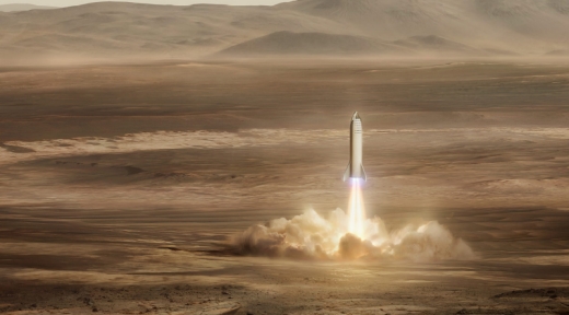
Image: Starship taking off from Mars. Credit: SpaceX.
If someone wanders the internet looking for articles on space, he is bound to run into the idea that the way to move forward in space exploration is to give all problems to SpaceX to solve, give all the money to SpaceX, everything is superior if it is made by SpaceX and that every other effort to solve any other issue in space is doomed at best, a waste of resources at worst, only SpaceX can solve everything. The triumphalism you find online about SpaceX gets quite annoying. My first reaction when I ran into this kind of articles and comments on internet boards was that these might be paid trolls. Closer scrutiny has shown that this is not the case, the posters are often true believers, and indeed inside SpaceX many truly believe that they are the salt of the Earth, or I should say the salt of space. My next reaction though would be, did they not do the Iliad in school in order to learn its lesson of hubris, ate, nemesis? Didn’t they do Herodotus in school, or the tragedies of Aeschylus, Sophocles and Euripides? Has classical education dropped so low in the West?
Then I ran into a Wired article entitled “Dr Elon & Mister Musk: Life inside Tesla’s production hell” [https://www.wired.com/story/elon-musk-tesla-life-inside-gigafactory/]. After he became a millionaire Elon Musk founded SpaceX, Tesla Motors and SolarCity with a utopian vision to change the world for the better. The foundational aspect of the companies is that the current methods in each industry are hopelessly outdated and that through disruptive innovation you can change the world for the better. Work hard enough (i.e. no 8 hour days; have a job, not a life) and the impossible becomes possible unless it violates the laws of physics. This is a general mentality prevalent in Silicon Valley: it is the place that believes that through hard work you can pursue the dream, and a place where hubris is actually welcome. Since Tesla achieved what was though impossible in the past, they think that they will keep on doing it regularly in the future. However the article is an inadvertent story of hubris, ate, nemesis: Tesla designs a great mass market electric car and decides to build it in a highly automated robotic factory to minimize the number of workers. Elon moves the production date six months forward from the original plan (hubris). When he runs into trouble setting up the production lines, and gets in a foul mood after his breakup with Amber Heard, he fires people on a whim when he runs into them if they are not able to answer his questions on the spot to his liking (ate). In the end he realizes that conventional car production companies are not the outdated behemoths he thinks: They have made a real effort to automate more and are already working at the edge of the possible. He manages to deliver his production goal, but 6 months after his original planned date and 12 months after the target date he set, $10,000 more expensive than the cost target and with his company a few weeks from bankruptcy (nemesis). The main thing going for the Tesla Model 3 is that it is a better electric car than the competition.
The relevant question here is, has he been chastened enough by the experience, or will he repeat the same hubris with his Mars plans? Incidentally, Elon’s treatment of his employees would never fly in Europe: if his firings are as arbitrary as described, his ex-employees have a right to sue and force him to hire them back at Tesla Motors. Also the idea of more than 8 hours work on a permanent basis and a general dislike of the idea of people taking vacation is reason enough for a European government to force an ultimatum: either respect the sacrosanctity of the 8 hour work and vacation for your employees or we will shut you down and fine you into personal bankruptcy. California simply does not have strong labor protections by European standards.
The SpaceX plan depends on the development of a monster rocket, larger in size and more complex than any other rocket produced in history, currently called the Super Heavy. The first stage will have 31 Raptor engines and launch the upper stage, currently called “Starship”, into earth orbit before returning for a landing and eventual reuse. The Starship, which will be able to transport 100 people to Mars and 100 tons of cargo, will be refueled in orbit by a tanker which will be a specialized version of the Starship that only carries fuel, and then launch to Mars. The trip is estimated to last between 80 and 150 days each way. On Mars SpaceX will help build an entire city. The timeline is pretty aggressive: In 2019 a Grasshopper like test vehicle for the Super Heavy will be completed; indeed Elon Musk has shared its images as it is being built from his Texas site. Then in 2020 the first full configuration Super Heavy will be launched to space. In 2022, as part of the #dearMoon project, Japanese billionaire Yusaku Maezawa and 6 to 8 artists will be launched on a weeklong trip around the Moon. In 2024 the first expedition to Mars, composed of two Starships, will be sent to land there and begin the process of colonization.
SpaceX has a history of running late, missing its goals and being secretive with the status of its programs. While the development states and the mishaps of the Space Launch System are quite public, with regular reports for example appearing on the site of the NASA Advisory Council (https://www.nasa.gov/offices/nac/home/index.html), it is quite hard to track the development and the milestones of the Super Heavy. It took an extended effort by the contributors and forum members of NASASpaceflight.com to produce this article (https://www.nasaspaceflight.com/2018/08/evolution-big-falcon-rocket/) with all the redesigns the mission has gone through based on the official presentations and the scraps that get dropped. Tracking the status of the Super Heavy has the feeling of Kremlinology. Elon Musk himself admitted during the first launch of the Falcon Heavy rocket that he almost cancelled that rocket three times, as he has already cancelled the Red Dragon mission to Mars.
Building the Super Heavy is an unprecedented endeavor. So far the only rocket that had so many rocket engines on its first stage was the Soviet N-1, which failed in all four attempts to launch. Now the first stage of the Falcon Heavy contains 27 engines, so SpaceX does have experience in properly starting that many rockets without destroying the vehicle. Raptor development, partially funded by the United States Air Force, seems to be proceeding normally, though again we do not really know. The Air Force funded the Raptor as an upgrade to the upper stage of the Falcon 9 rocket, which is considered underpowered. Elon Musk, though, has stated that its first space flight will be in the Super Heavy, so it will not see earlier activity that would help work out its kinks. Some risk will be retired by having it power the Grasshopper like prototype, but having an unprecedented number of unproven engines is major risk factor. NASA’s contractors have run into unexpected problems making the gigantic tanks and stages of the SLS because no one had built them to that size before with modern methods. What problems will SpaceX run when making its even bigger tanks?
My main issue, though, is with the Starship. SpaceX’s experience with crewed spaceships is limited to the Crew Dragon. SpaceX has never built a space station module or something similar. The Crew Dragon is to carry 7 people and is not intended to provide life support for months on end. For that matter, the most people that have been in space at one time was 13, when STS-131 visited Expedition 23 on the ISS.
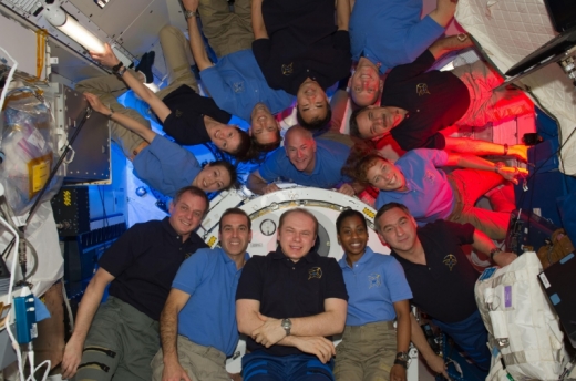
Image: STS-131 visiting Expedition 23. Credit: NASA.
No one has ever flown 100 people in space, and this on its own creates its own set of technological problems to solve. When Elon Musk unveiled what was then called the Interplanetary Transport System in the International Astronautics Council of 2016 in Guadalajara, per the reporters the most cringe worthy question was what he will do about sanitation. Elon brushed it off, but it is a very valid concern. The average American consumes a little under one ton of food per year. Now this is considered large and wasteful, so let’s assume that the average astronaut on the trip will consume 500 kg/per year. At 100 people and for three months that means 12.5 tons of food. I do not know how much human waste that will produce; as an agronomist, my know-how has been on animal waste, but even with a low residue diet similar to what the Apollo astronauts ate, it still means several tons. Current ISS technology is to boil the urine, recover some 75% of the water as vapor and throw away the brine containing the other 25%. Feces are dried and rejected overboard.
While this kind of technology will work on earth orbit, and is planned for the LOP-G, it can be quite problematic for a protected destination such as Mars. If you are to reject something overboard while on a Trans Mars Injection orbit, it will simply follow you on the way to Mars. Would we really want to drop a hygienic bomb weighing several tons on to Mars with the colonists’ untreated waste? On cruise ships on earth waste treatment is similar to what is used on land before the treated effluent gets rejected overboard. First there comes primary treatment, using mechanical methods such as gravity-based separation and filtering to remove any debris from the wastewater. Then comes secondary treatment, with the microbes on the waste allowed to grow and consume all the nutrients in the wastewater, turning into what is called activated sludge or biosolids, which are then removed. Then in tertiary treatment methods such as UV radiation and chlorination are used to reduce the bacterial load, up until the treated effluent is often of superior quality to tap water. Needless to say nothing of this sort has been tried in microgravity. On top of everything, what is currently recognized by the National Academy of Science as the hardest technical problem of the Mars trip, Entry Descent and Landing (EDL) on Mars, is just hand-waived.
It is generally recognized that the biggest hurdle that SpaceX will face is raising the money. The more modest NASA plan to Mars was estimated in 2017 to cost $221 billion by the NASA Office of Inspector General, and cost estimates at this stage of a project tend to be lower than the final cost. Estimates of the development cost of the Super Heavy, coming from outside SpaceX, are in the order of $5 to $10 billion. The cost of the NASA Space Launch System alone is $8.9 billion until the first launch, and SLS does not include the development of a new engine. The total cost of SLS, Orion and ground architecture, along with earlier Constellation costs for NASA, are at $26 billion until EM-1. SpaceX has a proven ability to develop and manufacture rockets at a cheaper price than traditional manufacturers, but if the Tesla Model 3 proved anything, it is that there are limits.
Let us be generous and assume that the whole Super Heavy, Starship and ground infrastructure all the way to the first mission to Mars will cost only $20 billion, which is generously low considering the technology development required. Where will this money come from? The space launch market is simply not large enough. SpaceX believes that since they will have the largest and most economical rocket in history, every commercial payload will gravitate towards them. The Saturn V was the most economical rocket in cost per weight launched, yet it never launched any payload outside the Apollo program. The Energia rocket was cheaper per kg than any other rocket at its time and was made available for commercial uses, but there were no takers. Granted, it did not have the payload adapters of Ariane 5, which is the first rocket designed from the start to launch multiple satellites in one launch. If you follow the news, Arianespace has trouble synchronizing the delivery and integration of two payloads. Very often delays on one payload mean that the other which is ready has to delay its launch to wait for it, or at best Ariane switches around payloads with a future mission if the delays get out of hand. SpaceX will somehow be able to get 10 large commercial payloads from different manufacturers and clients synchronized for a single launch. Ignoring for a moment political demands even for commercial operators to use national launchers. Satellite owners will wish to put all their eggs in one basket, considering that they do fear a launch monopoly.
The other potential use of the Falcon Heavy is in very fast long range travel. The USAF has been quite interested in having the ability to transport troops across the world in a ballistic missile since the 1960s and has had talks with SpaceX. If we are talking about commercial passengers, it is quite debatable how realistic this is. Per SpaceX’s own presentation the mission will be from some specialized terminal out at sea near city A to another specialized terminal out at sea near city B, with the sea commute taking some 45 minutes to and from cities A and B. Left unsaid is the bureaucratic hassle on entering countries unfriendly to foreign visitors: an international visitor entering the US through JFK airport on a busy afternoon might take two hours just to cross immigration even when said visitor has all the valid paperwork. Somehow a ballistic trip lasting less than an hour between London and New York looks less appealing if you need to spend 3 hours just to enter the US.
While SpaceX is a private company and does not publish its financials, leaked financial stated show a company that was profitable in years they did not have a launch mishap, and loss-making in years that they did. They have recently raised some $500 million from private equity which has allowed the construction of the model Super Heavy Grasshopper, but is also supposed to build the Starlink communication cubesat constellation. Two prototypes have already been launched to orbit, though none of them managed to reach their proper orbit after release. The leaked SpaceX plan expected that the profits from Starlink will be such that they will be financing Mars colonization. Be aware though that Starlink is not the only communication cubesat constellation planned; there already are other competitors with prototypes in space, and there is no shortage of satellite bandwidth in the current market. As an article noted, Elon will be competing not only with satellite manufacturers but also with established ground telecommunication companies such as Verizon. Elon will need to keep on doing six impossible things before breakfast for quite some time in order to succeed in his plans, though in his defense, he has achieved things once thought impossible.
NASA and other plans
In my opinion, the most mature Mars exploration plan ever proposed was the Soviet plan from 1989. RKK Energia proposed assembling a transfer vehicle based on Mir technology and sending it off to Mars using the Energia super heavy rocket. Considering that Mir derived modules form what is currently the Russian segment of the ISS and have proven reliable and that Energia flew twice in the 1980s, it was more realistic than many plans that wanted a new mega rocket on newly built modules. It should be noted, though, that the Soviet Union never had a fully successful Mars mission. Exomars, which is a joint ESA/Roscosmos mission is the closest thing to a fully successful mission the Soviet Union and its successor state Russia has had yet. NASA on the other hand has been sending successful robotic missions to Mars since 1965. This however has not translated to human missions yet. In the run up to the Moon landing Congress had a session in 1968 where NASA proposed that the next step after the Moon should be Mars. Congress turned down the offer. It was President George H W Bush that first put a Mars Landing as a national goal in his Space Exploration Initiative, along with the Space Station and a return to the Moon. Very little came out of SEI: While the Space Station was built, though with Russian participation for proliferation reasons, out of the Mars section all that came out was the Mars Program Office at NASA that has mostly coordinated robotic missions and the Design Reference Mission 1. As a reaction to DRM 1 came out Robert Zubrin’s Mars Direct plan, elements of which were eventually integrated in NASA planning. The next administration to pursue Mars as a target for human exploration was the George W Bush administration with its Vision for Space Exploration and its Constellation program, though only after the return to the Moon. Under Barack Obama the Journey to Mars was the main goal of the space program, though that administration never waged political capital to keep it well funded. The current Trump administration per Space Policy Directive 1 wants to go first to the Moon and pretty soon. SpaceX might simply win a Mars race by default.
The current Design Reference Mission to Mars is version 5, delivered in 2010 a little before the cancellation of the Constellation program. A Shuttle derived mega rocket, then the Ares V and currently the Space Launch System, will launch several times with the segments of a transfer habitat, which will be assembled in low earth orbit. A space tug powered by high power electric propulsion will send the habitat to Mars orbit, where it will rendezvous with a prepositioned ascent descent vehicle. Astronauts will land at the surface near the prepositioned rocket In Situ Resource Utilization fuel factory that will be creating methane fuel and oxygen from the Martian atmosphere and explore the region. The first mission will explore the surface for 30 days, but eventually the plan is for 200 day stay opposition missions. The ascent vehicle will refuel from the fuel factory and return the crew to the transfer habitat, which the tug will then send back to earth. The Orion deep space vehicle attached to the habitat will return the astronauts to the earth’s surface.
This particular architecture, while differing in details, has been the standard since the mid-1990s. Critiques have been that this plan does not create significant infrastructure and it will only lead to flags and footprint moments like Apollo with people not returning for decades. These plans suggest that first we should put up things like a fuel depot in an Earth-Sun Lagrange point or set up Aldrin cyclers between Earth and Mars to ensure routine transportation to Mars. Another critique is that this plan uses expendable architecture significantly and that we should be using only reusable rockets like the Falcon 9. Also Orion was not originally designed for Mars, so its heat shield is insufficient for several return orbits, and that instead the SpaceX Dragon should be used. Before Elon Musk made his big architecture announcement in Guadalajara there was a plan making the rounds in the literature, including papers by people working for NASA, that the preferred plan to Mars should be as such: Falcon Heavies and Falcon 9s should launch a transfer habitat similar to the Bigelow Expandable Aerospace Module with some specialized materials needed for the trip and Dragons, instead of SLS launching conventional habitats and an Orion. I never quite understood how the ascent/descent vehicle would get to Mars, most likely they would use a Crewed Dragon similar to the unmanned Red Dragon concept, but it would land near an ISRU rocket fuel factory, be refueled there and return to the inflated habitat. I also never understood how the astronauts would ascend from Mars, but landing on Earth would be by Dragon, whose heatshield can withstand Mars reentry. After Bigelow announced that they had an agreement with ULA to design an adaptor for their inflatable module on the Atlas V and its replacement the Vulcan, and the announcement of the Interplanetary Transfer System, which became the Big Falcon Rocket and the Super Heavy, the BEAM/Dragon plan has faded from public view. Lockheed Martin, though, has proposed a variation to DRM 5, the Mars Base Camp. Instead of astronauts just using an ascent/descent vehicle parked in Mars orbit, there will be a fully-fledged space station, a Mars Base Camp, that will facilitate surface landing and allow telepresence operations at the Mars surface with low latency robots.
The Orion spacecraft and the Space Launch System are likely not the optimal solution to footsteps on Mars. They are, though, what Congress wants and what it is funding. Democracy is not a regime that produces the optimum solution but the consensual solution that most people can live with. As Plato noted, the best possible regime is an absolute kingdom ruled by a perfect monarch, and then in the next sentence he says that such a king does not exist in the real world. The Byzantine emperors proclaimed after adopting the Greek title basileus (king) in the 5th century that they were the perfect king of Plato’s description, but no one with an elementary knowledge of history would really proclaim that any of them was a perfect ruler. King Elon would likely be able to mobilize the national resources of the United States better than the current plan of Congress and create something superior, but by his choices to situate his company’s infrastructure and his policy not to subcontract but rather build parts in-house he has shown that he does not play well the political game.
The main selling point about the current NASA plan is that it mobilizes the army of contractors and their workers sufficiently to eventually produce the desired outcome. The Space Launch System uses mature Space Shuttle technology and can trace its lineage in Shuttle Derived Launch Vehicles all the way back to the 1980s. The Orion spacecraft may have been advertised as a modernization of the Apollo capsule, but I would say that its lineage is closer to the Space Station lifeboat, which was intended for cases when the Shuttle was grounded. In turn, the Space Shuttle is also a cautionary note showing how combining kit with a long heritage and high technological maturity can still lead to something with lengthy and expensive overruns when these are drawn into unprecedented combinations. The transfer vehicle will be, as mentioned earlier, an improved variation of the Lunar Orbital Platform Gateway, and considering that it uses highly efficient electric propulsion rather than chemical propulsion of the Spaceship it is in some respects more advanced. Getting the NASA plan accomplished, though, in the end requires a renewed focus on Mars, which is something currently not in vogue in either the White House or Congress. As for other national space programs, while there are paper plans similar to the DRM 5 architecture, I am not aware of concrete plans to actually bring them to fruition.
Asteroids
This section should perhaps be better entitled Small Bodies. Asteroids, whether Near Earth, in the Main Belt and more recently the Jupiter Trojans, have been a target of robotic exploration since Galileo encountered 951 Gaspa in 1991. Other small bodies, though, were visited earlier, with the International Haley Armada of 1986 and Phobos and Deimos visited in 1965 by Mariner 4. The various space agencies will keep on sending missions, with the Jupiter Trojans that are to be visited by the Lucy mission being the next new category to receive a mission. Human plans were active until the recent cancellation of the Asteroid Redirect Mission. When the Obama administration cancelled the Constellation program, the next step in space chosen was to be a visit to a Near Earth Asteroid, which did not require a lander to be developed. After sky searches failed to find an object in a proper orbit to be visited by astronauts on an Orion before it ran out of supplies, the Asteroid Redirect Mission was devised. A robotic mission would go to a small asteroid, bag it, and carry it to a distant retrograde orbit around the Moon. Since no appropriate sized asteroids were found, it was modified so that a boulder would be carried from an asteroid to Moon orbit so that astronauts could visit it. This mission received a lot of derision from both the scientific community and space enthusiast circles. Other people pointed out that NASA does not even have an appropriate spacesuit for visiting the boulder. For now it seems that the first small bodies that people will visit will be Phobos and Deimos in an Apollo 8-like test for a human mission to Mars. Space planners would like to test first-long term survival of a transfer habitat, and visiting Phobos and Deimos does not entail the risk of Entry, Descent and Landing on Mars. A lander to Phobos or Deimos can be adapted from a lunar lander, though the landing will be more like a docking. Spaceships that visit Mars can be adapted to visit asteroid destinations, but so far no one has proposed such a trip to the best of my knowledge.
The Giant Planets
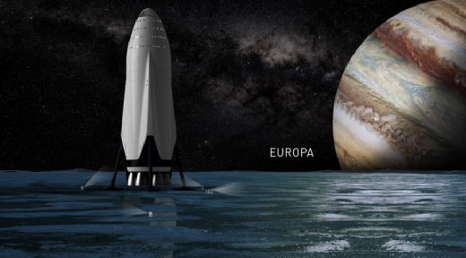
Image credit: SpaceX
In his 2017 Guadalajara presentation, Elon Musk included at the end graphics of his spaceship passing Jupiter’s Great Red Spot, on the surface of Europa, along the rings of Saturn and at the surface of Enceladus. A Hohmann Transfer orbit to Jupiter requires three times the energy and 3.4 times the time required to get to Mars, but if the Starship is as capable as Elon intends it to be, a Jupiter trip is within its abilities. So far this is the most concrete plan for a human mission to the outer planets: a series of graphics in a presentation of a spaceship that has been called by its detractors a fantasy rocket. Saturn is twice the distance to Jupiter, so the realism drops. There are, though, quite robust plans for robots to the giant planets.
Jupiter
The largest planet in the solar system has so far been visited exclusively by American space probes: Pioneers 10 and 11, Voyagers 1 and 2, Galileo, Cassini, New Horizons and currently Juno. Juno is the first solar powered space probe to Jupiter; the rest have been powered by Radioisotope Thermal Generators. It will be joined in the next decade by two other solar powered probes, ESA’s JUpiter ICy moons Explorer or JUICE and NASA’s Europa Clipper. NASA has plans for another mission to Europa, the Europa Lander. Funding for both Europa missions was found by Republican Texas Representative John Culberson. Since he lost his reelection bid, both missions are in peril. While the Clipper has the support of the broader scientific community, the Lander does not. Both missions currently expect to be launched on the SLS, which is a risk factor per advocates of the space science community since it is not certain that the rocket will not be cancelled and bring down the probes with it, as happened with the Mars Voyager program in the 1970s. While Clipper has a direct ascent trajectory to Jupiter, the Lander will do a tour of the inner solar system, like JUICE, to pick up orbital velocity in order to reach Jupiter. There it will land on Europa for a battery-powered mission that will last a few hours. The scientific community would prefer to launch a lander after the Clipper has sent back information, and follow it up with an ice drilling mission, somewhere in the 2030s. China and Russia also have preliminary plans for missions to the Jupiter system which are not as publicized as NASA’s and ESA’s plans.
Saturn
After the end of the Cassini mission in 2017, the most expensive space science mission in history, Saturn is without a robotic presence. But there have been several proposals in the most recent NASA Discovery and New Frontiers mission proposal requests. One of the finalists in the 12th Discovery competition was the Titan Mare Explorer (TiME), also known colloquially as the Titan boat, to drop a floater in one of the hydrocarbon lakes of Titan. In the current New Frontiers proposal, round one of the two finalists is the Dragonfly mission. It is a concept for a nuclear powered drone in the skies of Titan. The other object of interest at Saturn is Enceladus, which has an underground ocean. The Enceladus Life Finder was proposed in the recent 13th Discovery competition, but was not even shortlisted.
The mission has been reworked into a proposal that might become the first private planetary mission, to be funded by Yuri Milner to the tune of $60 million. A solar powered small probe will fly by the South Pole of Enceladus while it is erupting and collect a sample. While the probe is leaving the Saturn system (it will not enter orbit), it will analyze the sample with modern analytical equipment, rather than the vintage 1990s equipment that Cassini had. Private space probes have been proposed since the start of the space age, but have not come into fruition yet. Most recent was the Sentinel Space Telescope from the B612 foundation that was to scan the skies in an orbit between Earth and Venus so as to catch asteroids coming from the sun side of Earth. While they did raise some $2 million, this was far less than the $500 million they needed according to their budget estimates. SpaceIL has managed to raise $95 million for its lander to the Moon through philanthropy, and Yuri Milner has given to both his exploration initiatives (Breakthrough Starshot and Breakthrough Listen) some $200 million, so the Enceladus mission may happen, assuming it can surpass any problems that arise during development.
Uranus and Neptune
The two ice giants have only been visited by Voyager 2 in 1986 and 1989 respectively. The logical progression is that they are to be visited by orbiters. There have been several proposals both for NASA and ESA over the years and a Uranus orbiter was the third priority flagship mission in the most recent Decadal Survey of the Planetary Science community, after the Mars caching probe which became Mars 2020 and a Europa Orbiter which became the Europa Clipper. In preparation for the next Decadal Survey, a study was performed by the ice giants community that found that there is compelling reason to visit both, and that it is more of an issue of orbital mechanics which one to select. Four options were studied, from a Uranus flyby with an atmospheric probe to orbiters for both planets. The missions assume launches on the SLS. The cheapest option would be a tad less expensive than Cassini/Huygens; the more ambitious missions would dethrone it as the most expensive space probe.
NASA headquarters apparently lacks sufficient manpower to supervise multiple flagship missions, and lack of supervision was one of the main reasons that the James Webb Space Telescope has suffered delays and cost overruns. If Europa Lander continues, we are not likely to see a Uranus or Neptune mission, and even if it is cancelled the situation is quite dicey, because Congress would need to appropriate the funding and the Government Accountability Office grant a New Start. In a recent paper by members of the New Horizons team, they calculated trajectories with flybys of the outer planets that would lead to Kuiper Belt objects. In one of the summer schools at JPL, a student team proposed a Uranus mission that would fit inside a New Frontiers budget, which if proven correct would be something that the scientific community would rally behind. So far, though, a mission to the ice giants remains in the realm of proposals. Perhaps in the next decade one of them might get selected leading, to a mission that, if all goes well, should arrive at one of the ice giants in the middle of this century.
The Kuiper Belt and the Oort Cloud
When I was growing up, the Solar System, which was the only planetary system known, had 9 planets. I got interested in space with the Neptune flyby in 1989 and I was looking forward to a mission to the last planet, Pluto. I had to wait another 26 years until New Horizons flew by Pluto, which at that time had been demoted from planet, a mistake in my personal opinion. New Horizons just encountered 2014 MU69, nicknamed Ultima Thule by the New Horizons team, and it is currently sending back the data it collected. New Horizons scientists hope to fly by another object in the Kuiper Belt, though that would have to be discovered first. When the Voyagers crossed the Kuiper Belt it was still a theoretical concept; the first object other than Pluto was only discovered in 1992. Today some 3,000 objects are known, and some such as Sedna are considered likely to belong to the even further out Oort cloud, the origin of comets. Several comets have been encountered in the inner solar system but Ultima Thule is the first such object visited in its native environment. Scientists have proposed several planetary sized objects in the outer solar system, the most famous being Planet 9, which so far are all theoretical. There have been proposals to visit again this part of the solar system, the most mature of which was New Horizons 2, which would have been built from the spare parts of New Horizons and sent to Eris via a Uranus flyby, but none have moved beyond studies on paper.
Interstellar Space

Image: Concept poster of the JHUAPL interstellar probe. Credit: Johns Hopkins University.
This is a blog on interstellar travel, so many mission concepts using various engine technologies have been published here. I am limiting myself here to missions that use more mature technologies. In 2012 Voyager 1 became the first spacecraft to pass the heliopause and enter interstellar space. Its twin Voyager 2 followed it in 2018. New Horizons will follow them sometime in the future, if it does not run out of power earlier. New Horizons is headed towards the IBEX ribbon, which the Voyagers missed because they are headed far from the ecliptic. Missions to the heliopause and beyond have been proposed by the heliophysics community since the start of the space age, but were not approved due to their high cost and risk.
There is currently a proposal for an interstellar probe being created by JHUAPL to be part of the next Heliophysics Decadal survey. The most accessible online summary of the proposal is at the FISO Telecon Archive at http://fiso.spiritastro.net/telecon/McNutt_9-5-18/ from a September 5 2018 presentation. There were also updates for the proposal at the 69th International Astronautical Congress in Bremen in October 2018 [http://iafastro.directory/iac/paper/id/44169/summary/] and at the 2018 Fall AGU meeting in Washington in December 2018. The Bremen presentation led to a Space.com article [https://www.space.com/42935-nasa-interstellar-probe-mission-idea.html]. There were two sessions at AGU dedicated to this proposal according to the online program, one of oral presentations and one poster session. Some of principal investigator’s Ralph McNutt’s slides have appeared online and someone did tweet with the hashtag #InterstellarProbe about one of the oral presentations at the AGU about dust in the Kuiper Belt. In the same session there was also talk of a Chinese interstellar probe, but I was not in Washington DC for AGU and I am not an AGU member in general so I do not know anything about that beyond the AGU summaries. I will try to summarize my understanding of the proposal based on what has been posted online.
The proposal as mentioned is for the next Heliophysics Decadal Survey and is to be delivered to NASA in February 2019. The scientific case for the mission is good; the Voyagers have whetted our appetites rather than solve the major questions about interstellar space. The problem with the Voyagers and New Horizons is that they were optimized for the planets; for that matter New Horizons does not even have a magnetometer because they would need amagnetic versions of the rest of its instruments, which would have doubled their cost. The goal is to have a probe at a distance of 1,000 AU in the time of 50 years. For this they would have to have it travelling at least twice the speed of Voyager 1. The probe will weigh in the same range as New Horizons (478 kg) or the Parker Solar Probe (685 kg), both of which are JHUAPL probes. Three options are being studied: an Oberth maneuver around the sun with a solid rocket stage to be carried at 4 solar radii from the surface (closest Parker approach is 8 solar radii); a powered flyby of Jupiter; and a New Horizons-style solid-fuel earth departure stage with Jupiter gravity assist. The launch vehicle so far is the SLS Block 2. Since they will be visiting the region they will also encounter a Kuiper Belt Object such as Quaoar, Ixion or Haumea. The fastest option currently, at 12 AU per year, would be a CASTOR-30XL upper stage using an Oberth maneuver around the sun, but at 50 years it would only get them to 600 AU or so.
We will not have to wait long for the report if it is released. Is NASA Heliophysics willing to go forward with this mission? So far, after the Parker Solar Probe and US participation in ESA’s Solar Orbiter, NASA Heliophysics does not have any flagships coming up. The longevity of the Voyagers, though, has shown several problems that arise in long lived probes. The Voyager team is hoping to push both probes to be active 50 year after their launch in 2027. Due to the decay of their RTGs they will have to start turning off instruments soon because there will not be enough power anymore for all of them. The Voyagers are the only mission that still mostly communicates in the S band with the Deep Space Network, so NASA is keeping old equipment just for them. Both are so far out that the minimum speed of their tape playback is higher than the maximum communication speed, so data is lost when played back to earth from the tape. On top of everything, with both Voyagers being built with 1970s technology that means that they are using computational tools of that time. When a website reported inaccurately that they were looking for a programmer that knew their archaic version of FORTRAN because one of their coders was retiring, the people that came forward on the web were also septuagenarians because of the obsolescence of that language. Which of the current programming tools will still be used some 50 years from now? As someone who constantly deals with unsupported computer systems as part of my day job, this is something that I relate to. Voyager 1 is currently at 145 AU and travelling at 3.6 AU/year. In 2027 it will be at 175 AU, a distance record that it will definitely hold for decades. The interstellar probe is intended to reach over 5 times that, which will require upgrades of the DSN.
Conclusion
There are many technical issues that arise in the process of space exploration, but so far I think that the biggest problem is money and interest. A spaceship to Mars can open the solar system from Mercury to Jupiter for human exploration. The NASA Office of Inspector General estimate for its Mars plans was at $221 billion for two missions to Mars, while the estimate of the National Academies of Science was at $300 to $500 billion. SpaceX believes that they can do this mission for a fraction of the cost with a rocket and a spaceship that will be more capable than anything ever built. They also believe that they can raise the money through their activities. On the robotic side, there are many interesting destinations, far more than what the budgets and oversight capacity can buy. It would be interesting to reread this article in a few years and see what has actually come to fruition from all these plans.
What’s Next for New Horizons?
The exuberance of images like the one below captures the drama of Solar System exploration. Scenes like this are emblematic of the early reconnaissance of the Solar System. We saw similar enthusiasm with missions near and far — I’m thinking back, for example, not just to Voyager, but the Viking landings on Mars, and I’m sure Russian controllers were equally jubilant when their Venera craft touched down on Venus. Space is indeed the ‘final frontier,’ as James T. Kirk reminded us on Star Trek, and it’s a frontier that goes on without end.
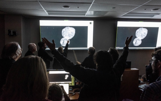
Image: Celebration in full swing as scientists react to the view from New Horizons after the Ultima Thule flyby. Credit: NASA / JHUAPL / SwRI / Henry Throop.
Let’s keep in mind, then, that New Horizons is not just returning Ultima Thule data, but continuing to push into the Kuiper Belt doing good science. In terms of future missions, we need to learn as much as we can about radiation, gas and dust as we assess the environment. New Horizons will get an extended mission, we can hope with some justification, because after all, a fully operational spacecraft operating in this far region is a unique, invaluable resource.
But we don’t have to wait for an extension to continue exploring Kuiper Belt objects, even if no flyby is possible. I’m thinking of one called 2014 PN70, which will be observed in March. As mission principal investigator Alan Sterne notes in this latest report, this KBO was a proposed flyby target before Ultima Thule was chosen, losing out at least partly because it required more fuel to reach than Ultima.
Although the spacecraft won’t be able to see it up close, we should still be able to assess 2014 PN70’s shape, surface properties and rotation rate, as well as look for possible satellites. Discovered in Hubble observations, the object is known to be about 40 kilometers in diameter. New Horizons will be unable to resolve 2014 PN70 or another early flyby candidate, 2014 OS393, but study of both will help put the accumulating Ultima Thule data in perspective.
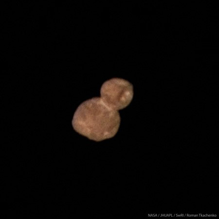
Image: Ultima Thule as seen in color by New Horizons during its close approach. Credit: NASA/JHUAPL/SwRI/Roman Tkachenko.
Recovering the entirety of New Horizons data on Ultima Thule will take 20 months, and recall that from January 4 to 9, controllers had to wait because the spacecraft was obscured by the solar corona, making communications problematic. At this point, the team has just 1 percent of all the Ultima Thule data. Hundreds of images and spectra remain to be downloaded, but the process of compiling science results is already well underway, with 40 abstracts submitted to the 50th Lunar and Planetary Science Conference, to be held in Houston this March.
What a primitive place Ultima turns out to be, a fact which comes as no surprise. In the abstract for his talk in Houston, Stern summarizes its nature this way:
New Horizons has revealed MU69 to be a bi-lobate contact binary that appears to have merged at low speed. In addition to being the most primitive solar system object ever to be explored in situ by any spacecraft, MU69 thus also becomes the first primordial contact binary. The appearance and contact binary nature of this object is consistent with it being a relic planetesimal possibly created by pebble accretion. How MU69’s two lobes merged, how gently, and how much angular momentum was lost prior to contact are puzzles to be solved as more data are returned and detailed modeling can be undertaken.
Ultima Thule, then, as well as other Kuiper Belt objects we’ll study with New Horizons and later missions, becomes a key to the formation era of the Solar System, offering potential insights into planetary accretion. The available data have revealed no evidence of rings, a moon or an atmosphere, though we have to hold on that point until the dataset is complete. Differences in surface reflectivity are clear, including the striking brightness of the connecting ‘neck’ between the two lobes (the larger of which is now nicknamed Ultima, the smaller Thule).
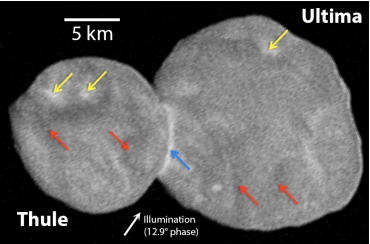
Image: This is Figure 1 from Stern’s abstract. Caption: Ultima Thule as seen by the LORRI imager in the close approach CA04 observation (140 m/pixel), including relatively bright circular patches a few km wide (yellow arrows), darker regions up to several km wide (red arrows), a bright, cylindrically symmetric neck (blue arrow), and quasi-linear and arcuate bright features; note also the mottled appearance. Credit: JHU/APL; Alan Stern.
On the matter of dust, this is interesting:
Regarding dust near Ultima Thule, New Horizons saw no evidence down to I/F~5×10-7 in imaging available by 4 Jan 2019. In addition, zero impacts onto the New Horizons dust counter were detected inside MU69’s Hill sphere. And no satellites were detected down to 1.5 km diameter (under the assumption of an Ultima Thule-like reflectivity) outside of 1000 km from Ultima Thule. A search for closer rings or satellites has not yet been performed.
If New Horizons gets that extended mission, it should begin in late 2021. The good news that Stern passes along in his PI’s Perspective is that the spacecraft was able to conserve some of the fuel that had been allocated for the Ultima Thule flyby. Fully operational and with a potent science package, New Horizons is good to go for further Kuiper Belt exploration.
‘Oumuamua, SETI and the Media
One of the more important things about the interstellar object called ‘Oumuamua is the nature of the debate it has engendered. Harvard astronomer Avi Loeb’s paper examining it as a possible technology has provoked comment throughout the scientific community, as witness Jason Wright’s essay below. Dr. Wright (Penn State) heads the Glimpsing Heat from Alien Techologies (G-HAT) project, which he described in these pages, and is a key player in the rapidly developing field of Dysonian SETI, the study of possible artifacts as opposed to deliberate communications from extraterrestrial civilizations. Here he looks at the debate Loeb’s work has engendered and its implications not only for how we do science but how we teach its values to those just coming into the field. Jason’s essay was originally posted several days ago on his Astrowright blog, which should be a regular stop for Centauri Dreams readers.
by Jason T. Wright

Avi Loeb is the chair of the astronomy department at Harvard, a distinguished and well cited astronomer (he has an h-index of 87), and the chair of the Breakthrough Starshot initiative. He’s a strong proponent of making sure that science doesn’t succumb to groupthink and champion of outré ideas.
He also has been making headlines recently for articles he has co-authored, interviews he has given, and popular media columns he has written about the possibility that fast radio bursts, and now ‘Oumuamua, are artificial in origin. This has created a great deal of buzz in popular culture and a lot of hand-wringing and criticism on social media by scientists who find his actions irresponsible. Many have asked my opinion, so I’m collecting my many thoughts on the topic in this post.
I am happy to defend Avi on these grounds:

- He is driving us to have an important conversation about what “acceptable” SETI research looks like, and in this conversation I’m mostly on his side. He’s essentially moving the scientific equivalent of the “Overton Window” towards SETI, and that’s a good thing. These are exciting and interesting questions and we should not let the face-on-Mars/Ancient-Aliens/UFOlogy types prevent us from discussing them.
- He is using tenure and his stature the way we all imagine it’s supposed to be used: as a shield so that he can explore potentially unpopular research avenues without fear of retribution or ostracism. We all imagine that’s what we would do in his position (I hope!) but too often it ends up just being a club to get junior scientists to conform to one’s vision for what “proper” science looks like and what “good” problems are.
- The papers he and his postdocs are writing are important first steps in making Solar System and other forms of SETI a serious academic discipline.
- He is being a role model for how scientists can explore outré ideas and spend an appropriate amount of their time on potential breakthroughs.
- He is putting SETI in the public eye and doing a lot of outreach.
Image: Harvard’s Avi Loeb, at the center of the discussion of ‘Oumuamua. Credit: Harvard University.
Avi wouldn’t be pushing the envelope hard enough if he weren’t getting some pushback, and indeed there is plenty of fair and good-faith criticism that can be made about his approach (not all of which I agree with):
- The degree of certainty he expresses in ‘Oumuamua being artificial does seem unwarranted to me (though to be fair I’ve always been an ‘Oumuamua-might-be-artificial skeptic.)
- Given the way we know the press (especially the yellow press) will handle any story about “aliens”, one can argue that the “extraordinary claims require extraordinary evidence” maxim is especially applicable to SETI (I’ve made this argument strongly when discussing my own research in the press.) Avi could hew more closely to this maxim.
- The tone of his papers and his public comments are quite divergent. The body of the paper on ‘Oumuamua-as-lightsail, for instance, has a brief mention about the potential of the artifice of ‘Oumuamua at the end, but most of it is about the perfectly general problem of thin objects in interstellar space. Snopes highlights this divergence well pointing out that the paper is quite sober and restrained compared to some of the media coverage. (It’s true that the title and abstract of the paper are about ‘Oumuamua specifically, and that it serves as the case study for the whole analysis.) Avi’s public statements are much less conservative and equivocal.
- He is not just quietly following the evidence; he is using his platform to have a very public and high-visibility discussion about his research. I will concede that Avi is an exception to my earlier (somewhat petulant) protest that SETI scientists are not in it for the attention. That said, I will object to anyone who would claim Avi is only in it for the attention, or that such attention is inherently a bad thing.
- Many of his papers are de novo explorations of topics like the fate of comets in interstellar space, with little connection to the substantial amounts of work that has already been done on the topic, and his papers would be better and less naive if they had a closer connection to this prior work rather than starting from scratch.
Uh… I'll just say there's some relevant literature for the erosion of comets by the ISM. Also, the literature for lightcurves is pretty extensive. The paper does not attempt to show that a tumbling flat sheet is a non-rejectable fit to the available lightcurve data.
— Michele Bannister (@astrokiwi) December 26, 2018
More broadly, let’s look at two threads on Twitter criticizing Avi. I’ll start with this one by Bryan Gaensler:
New theories need to make predictions. If reality doesn’t match predictions, your theory is wrong.
The problem with aliens as a theory is that if your predictions fail, you can just give your aliens additional new powers and adjust your theory.
— Bryan Gaensler ?? (@SciBry) January 16, 2019
Bryan makes the rather Popperian argument that if your model is too flexible then it can’t be falsified, so you’re not doing science. The implication is that since we don’t have a good model for aliens, we can always play the “aliens of the gaps” game and so SETI isn’t good science unless it’s looking for unambiguously artificial signals like narrow-band radio waves.
This argument isn’t as tight as it seems. Most interesting new theories start without concrete predictions—General Relativity was so hard to use that even Einstein wasn’t sure what it predicted (he got the deflection of starlight wrong the first time he calculated it; he wrote a paper saying gravitational waves don’t exist). Theories don’t spring fully-formed from theorists’ heads; many important breakthroughs start with something less than quantitative or precise (“maybe we need to modify gravity”; “maybe there is a new subatomic particle involved”) and let the data guide the theories’ details.
This is the normal progression of science. SETI is no different, and so no less scientific.
Then there is this one, by Eric Mamajek, which I mostly agree with:
1/n "when you have excluded the impossible, whatever remains, however improbable, must be the truth” – it is unfortunate that this Sherlock Holmes quote is being bastardized with respect to knew phenomena like #Oumuamua, #BoyajiansStar, and #FRBs. https://t.co/Iijp10STQj
— Eric Mamajek (@EricMamajek) January 15, 2019
It’s mostly fine through tweet #9, but then he conflates things in the last tweet using an unwarranted leap of logic.
10/n It does NOT serve science or public well when small num of *scientists* for whatever reason are pulling the "I'm not saying it's aliens, but we can't rule it out quite yet (wink)" for what will inevitably turn out to be mundane astrophysical explanations (e.g.rock, dust, BH)
— Eric Mamajek (@EricMamajek) January 15, 2019
Up until then he had been criticizing the Holmesian logic of how ‘Oumuamua must be alien because we had ruled out natural explanations. I quite agree with him.
But in the last tweet he jumps to criticizing even bringing up the hypothesis of ETI’s in general, implying that scientists who do are pulling a Giorgio Tsoukalos. (There’s also the assertion at the end such anomalies will “inevitably” turn out to be not just natural, but mundane, which is obviously not strictly true.)
But Tabby and I weren’t pulling a Tsoukalos when we submitted our proposal with Andrew Siemion to NRAO to study Tabby’s Star. We really weren’t. I have clarified the actual events with Eric, so I’m pretty sure that’s not what he meant to imply here, but that is how this tweet reads.
Bryan makes a similar (but softer) implication in his final tweets:
It’s wrong to say “it can never be aliens”. One day it may well be.
But I personally want something like:
• radio transmission of prime numbers
• oxygen or chlorophyll in an exo-atmosphere
• anything that’s actually impossible (not just tricky) to produce naturally
— Bryan Gaensler ?? (@SciBry) January 17, 2019
We all would! Indeed, it was Avi Loeb who made the suggestion that Breakthrough Listen point Green Bank at ‘Oumuamua [1] because he understands very well that the proof of alien technology is something like the bullets on Bryan’s list.
But the implications of these tweets aren’t just wrong, they’re harmful to the field of SETI. A very plausible path to SETI success will be that we will see something strange (not “Eureka!” but “That’s funny…” as the old fortune quip goes) and eventually, after lots of follow up, we might find the smoking gun, or perhaps it will just end up being a proof by exclusion. As I wrote in 2014:
Artifact SETI can thus proceed by seeking phenomena that appear outside the range that one would expect natural mechanisms to produce. Such phenomena are inherently scientifically interesting, and worthy of further study by virtue of their extreme nature. The path from the detection of a strange object to the certain discovery of alien life is then one of exclusion of all possible naturalistic origins. While such a path might be quite long, and potentially never-ending, it may be the best we can do.
Communication SETI, on the other hand, shortcuts this path to discovery by seeking signals of such obviously engineered and intelligent origin that no naturalistic explanation could be valid. Together, artifact and communication SETI thus provide us with complementary tools: the most suspicious targets revealed by artifact SETI provide the likeliest targets for communication SETI programs that otherwise must cast an impossibly wide net, and communication SETI might provide conclusive evidence that an extreme but still potentially naturalistic source is in fact the product of extraterrestrial intelligence (Bradbury et al. 2011).
Bryan’s thread and Eric’s final tweet could easily be read to foreclose this sort of research, essentially saying “it’s not worth thinking about the aliens hypothesis until it’s so unavoidable that you’ll get no flak for it” (radio signals à la Contact, the proverbial saucer on the White House lawn, etc.). They certainly make it clear that they won’t hesitate to chastise you on Twitter for going down this road.
But if we want to get to the end of that road, we’ve got to start walking down it at some point, and when the media very reasonably asks what we’re doing so they can report on it to a very understandably curious public, we should be allowed to answer their questions without having our motives (or scientific credibility) questioned by our peers.
In short: your mileage may vary on Avi’s particular style of public communication and conclusions on ‘Oumuamua, but when making your critique please be mindful that you are not slamming the whole endeavor. SETI as a serious science will make hypotheses, explore anomalies, and discuss the possibility of alien technology as the cause, and we need to be able to do so without obloquy from our peers, and without them policing which kinds of SETI we’re “allowed” to work on or talk about in public.
If I seem touchy about this, it’s actually not because I’m smarting from these Twitter threads or anything like that (which I don’t actually disagree with much—in particular I’m friends with Eric and I know I have his respect). As I wrote at the top, I’m glad we’re having this conversation and I hope it continues!
But another purpose of this post is that Avi and I (and other SETI researchers) have advisees that work on SETI and these sorts of messages are not lost on them: these tweets imply that senior people in your field will disapprove of you because of the topic of your research, and they will police what you’re allowed to say to the press, regardless of how good a scientist you are. Keep in mind, “Avi’s” paper on ‘Oumuamua that is being criticized has a postdoc as first author.
So in closing: I pledge to keep the SETI real and well grounded in science, to be responsible in my interactions with the media about it, and to train my students to do the same.
And, I hope my peers will pledge to create a welcoming environment for my advisees as SETI (hopefully!) comes back into the astronomy fold (even when—especially when—they are complaining about Avi).
[Updates: Bryan responds in this thread (click to expand):
In this blog piece, @Astro_Wright takes on the concerns and criticisms raised by me and by @EricMamajek, and does a great job of rebutting / clarifying / expanding / contextualising.
— Bryan Gaensler ?? (@SciBry) January 17, 2019
also:
[1] = privately, Bryan clarified to me his tweet was referring to his team’s MWA search for signals, not the search by Breakthrough Listen at Avi’s suggestion, as I suggested in my post. My point that Avi appreciates the importance of dispositive evidence stands, but I should have read Bryan’s tweet more carefully and followed link before critiquing his tweet.]
Also, I’ve changed the language about who suggested that GBT observe ‘Oumuamua; Joe Lazio informs me that the observations were made with WVU time following discussions with Breakthrough Listen that preceded Avi’s recommendation. In spite of both errors on my part in the original post, my point that Avi appreciates the importance of dispositive evidence stands.
Also, Avi touches on his motives in this interview:
But the search for intelligent life remains outside the mainstream. I am trying to change that in two ways. First, by speaking out in the way that I did on ‘Oumuamua.
A Disk at an Angle (and a Remarkable View)
One of the joys of science fiction is imagining landscapes. What would it be like to stand on Titan, for example, a question that was inescapably influenced in my youth by Chesley Bonestell’s wonderful depictions, as well as novels like Larry Niven’s World of Ptavvs (1966) or Michael Swanwick’s novelette “Slow Life” (Analog, December 2002). And then, of course, there were those multi-star skies, as in Asimov’s “Nightfall” (Astounding Science Fiction September, 1941.
The Science Fiction Writers of America, incidentally, voted “Nightfall” the best science fiction story written prior to 1965, when the Nebula Awards began. I would bet almost all Centauri Dreams readers are familiar with it, but if not, it’s widely anthologized.
And now we have another visual phenomenon to contend with, a landscape and its sky that had never occurred to me. A team led by Grant Kennedy (University of Warwick, UK) has discovered the first confirmed case of a multiple star system whose surrounding disk of gas and dust circles the central stars at right angles. The work grows out of data gathered with the Atacama Large Millimeter/sub-millimeter Array (ALMA). Says Kennedy:
“Discs rich in gas and dust are seen around nearly all young stars, and we know that at least a third of the ones orbiting single stars form planets. Some of these planets end up being misaligned with the spin of the star, so we’ve been wondering whether a similar thing might be possible for circumbinary planets. A quirk of the dynamics means that a so-called polar misalignment should be possible, but until now we had no evidence of misaligned discs in which these planets might form.”
So let’s imagine a planet forming in the dust ring, just as we know planets form in the disks we’ve found around single stars. From the surface of such a world, our new science fictional setting shows us the disk as a band rising out of the horizon, with the twin stars moving in and out of the disk plane, so that we get two shadows much of the time. Our circumbinary planet in its all but perpendicular orbit of the primaries might see a scene like the one below.
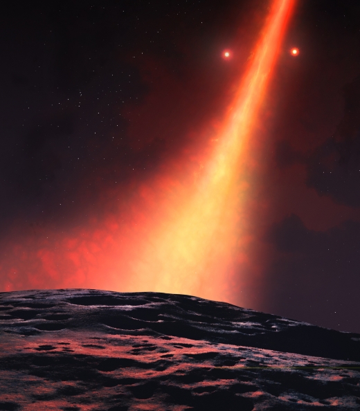
Image: View from an orbiting planet. Copyright: University of Warwick/Mark Garlick. Used with permission.
The young system in question is found at HD 98800, also known as TV Crateris, in the constellation Crater, somewhere around 150 light years away from the Sun. This is actually a quadruple star system found in the TW Hydrae association. HD 98800 A is a K-class dwarf probably orbited by a red dwarf, while HD 98800 B is likewise a K-class, red dwarf pairing. A planet in this system — and bear in mind that this is a very young system, so the planet-forming process would be early — would have four nearby stars to color its landscape.
The authors do not believe such systems are rare. From the paper:
If planet formation can proceed equally efficiently in both coplanar and polar configurations, circumbinary planets on polar orbits are predicted to be nearly as common as their coplanar brethren (although these fractions may be modified by later dynamical evolution). The most eccentric binaries are the most likely to have polar disk configurations, so it is not surprising that the known transiting circumbinary planets, which are near to coplanar, are all in systems with e?0.52, with 8 out of 9 having e<0.22… Polar disks, and perhaps planets, may be a common outcome of circumbinary disk formation, and provide motivation for systematic searches for both.
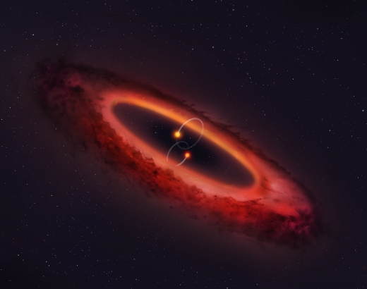
Image: View of the double star system and surrounding disc. Copyright: University of Warwick/Mark Garlick. Used with permission.
Is there, then, a large population of such unusually aligned circumbinary planets awaiting discovery? If so, we’ll have a variety of further interesting landscapes to consider, even as we ponder the kind of seasonal variations that can occur on circumbinary worlds circling a wide range of stellar classes and their own possible companions. Plenty of material here for writers, or has some far-sighted SF wordsmith already depicted such a planet? If so, please let me know in the comments.
The paper is Kennedy et al., “A Circumbinary Protoplanetary Disc in a Polar Configuration,” Nature Astronomy 14 January 2019 (abstract).
Follow with RSS or E-Mail